Dimension accuracy loss under load
- merongi
- Offline
- Junior Member
-

Less
More
- Posts: 37
- Thank you received: 13
19 Feb 2024 00:48 #293731
by merongi
Dimension accuracy loss under load was created by merongi
Hi,
I have 4060 type CNC converted to LinuxCNC with 7i95T.
This one has linear rail and 1605 ball screws, so basic constructions are there.
If I put dial indicator with 0.0001" resolution on spindle and test backlash, it's fraction of 0.0001".
Dial indicator is Mitsutoyo one, so measurement is reliable and very repeatable.
I step 1mm, 10mm or several 10's of mm and back to the starting edge, dial goes back to 0 (reference) or fraction of 0.0001" difference.
I tested both X and Y on this and got the same result.
I put digital caliper on the vice, set to zero, then step by pushing the head in one direction. Distance error is kept 0.01mm.
But, when I cut 20mm round object with Aluminum, X = 19.90 and Y = 19.80mm.
Around the cylinder surface, there are two humps. These two hump to hump, located around at 15 deg and 195 deg, distance are 20.08mm.
How can I reduce this error? Any help would be appreciated.
Thanks
Please Log in or Create an account to join the conversation.
- tommylight
-

- Away
- Moderator
-

Less
More
- Posts: 21767
- Thank you received: 7440
19 Feb 2024 01:13 #293733
by tommylight
Replied by tommylight on topic Dimension accuracy loss under load
Picture of the part?
Please Log in or Create an account to join the conversation.
- merongi
- Offline
- Junior Member
-
Less
More
- Posts: 37
- Thank you received: 13
19 Feb 2024 01:35 #293734
by merongi
Replied by merongi on topic Dimension accuracy loss under load
Here are the pictures I took to show how it looks like.
Dimensions are 20mm diameter cylinder with 5mm height.
12000rpm x 1500mm/min cut with 1/2" flat end mill, 3flt finishing, 5mm depth x 0.5mm width cut.
Dimensions are 20mm diameter cylinder with 5mm height.
12000rpm x 1500mm/min cut with 1/2" flat end mill, 3flt finishing, 5mm depth x 0.5mm width cut.
The following user(s) said Thank You: Mecanix
Please Log in or Create an account to join the conversation.
- tommylight
-
- Away
- Moderator
-
Less
More
- Posts: 21767
- Thank you received: 7440
19 Feb 2024 01:46 #293735
by tommylight
Replied by tommylight on topic Dimension accuracy loss under load
Yeah, that is backlash, probably on the ballscrews or on the screw bearing mounts.
Also from your dimensions it seems there is quite some runout on the spindle or bent endmill.
Also from your dimensions it seems there is quite some runout on the spindle or bent endmill.
Please Log in or Create an account to join the conversation.
- merongi
- Offline
- Junior Member
-
Less
More
- Posts: 37
- Thank you received: 13
19 Feb 2024 20:08 #293784
by merongi
Replied by merongi on topic Dimension accuracy loss under load
Thanks for looking into this and I have a couple of questions.
If this is backlash, how does it show up in 15deg from the Y axis?
I set dial indicator to 0 to a side of 1/2/3 block, jog out then back to the side. Dial indicator is <0.0001" off. So I'm not sure where the backlash is coming from. I may check screw bearing mounts. And it requires disassembly of machine, yay...
I'll try to measure runout of the tool and correlate with dimensional error.
Please Log in or Create an account to join the conversation.
- tommylight
-
- Away
- Moderator
-
Less
More
- Posts: 21767
- Thank you received: 7440
19 Feb 2024 21:15 #293791
by tommylight
Replied by tommylight on topic Dimension accuracy loss under load
Set the dial indicator on the endmill, base on the table, push against it.
Do this on all 4 sides, what deflection do you get?
Do this on all 4 sides, what deflection do you get?
The following user(s) said Thank You: merongi
Please Log in or Create an account to join the conversation.
- merongi
- Offline
- Junior Member
-
Less
More
- Posts: 37
- Thank you received: 13
20 Feb 2024 05:57 #293820
by merongi
Replied by merongi on topic Dimension accuracy loss under load
It was runout issue. Last time I measured runout, it was <0.002" but this time it's like 0.006". Checked the collet and there was a chip. Once I remove it, it went down to 0.0015", which is ~0.038mm. It may still create 0.1mm dimensional error though, but not 0.2mm.
Thanks!
Thanks!
The following user(s) said Thank You: tommylight
Please Log in or Create an account to join the conversation.
- besriworld
- Offline
- Elite Member
-

Less
More
- Posts: 317
- Thank you received: 85
20 Feb 2024 13:51 #293840
by besriworld
Replied by besriworld on topic Dimension accuracy loss under load
Usually, stepper motor drives make a similar defect.
Please Log in or Create an account to join the conversation.
- Mecanix
- Offline
- Platinum Member
-

Less
More
- Posts: 447
- Thank you received: 228
20 Feb 2024 15:05 - 20 Feb 2024 15:07 #293845
by Mecanix
Replied by Mecanix on topic Dimension accuracy loss under load
Excellent visuals. Runout or not, that infamous and consistent fish-scale effect left by the cutter on the surfaces indicate a severely out-of-tram Z. Start with a "how to tram your mill" tutorial, then once that's within spec move on to mapping linearity and accuracy of the screws with compensation files (see: wiki.linuxcnc.org/cgi-bin/wiki.pl?Screw_Compensation ).
That will take care of both your backlash and linearity/error. Done properly you should be able to mill a bore/boss within a 10~20um accuracy.
That will take care of both your backlash and linearity/error. Done properly you should be able to mill a bore/boss within a 10~20um accuracy.
Last edit: 20 Feb 2024 15:07 by Mecanix.
The following user(s) said Thank You: merongi
Please Log in or Create an account to join the conversation.
- merongi
- Offline
- Junior Member
-
Less
More
- Posts: 37
- Thank you received: 13
17 Mar 2024 06:00 - 17 Mar 2024 06:01 #296106
by merongi
 I fixed Tram in Y axis with grub screw but X axis fix requires some modification of spindle holder, so it would take some time and will be done after current project.
Meanwhile, I think I found the source of backlash under the load but I don't know how to fix.
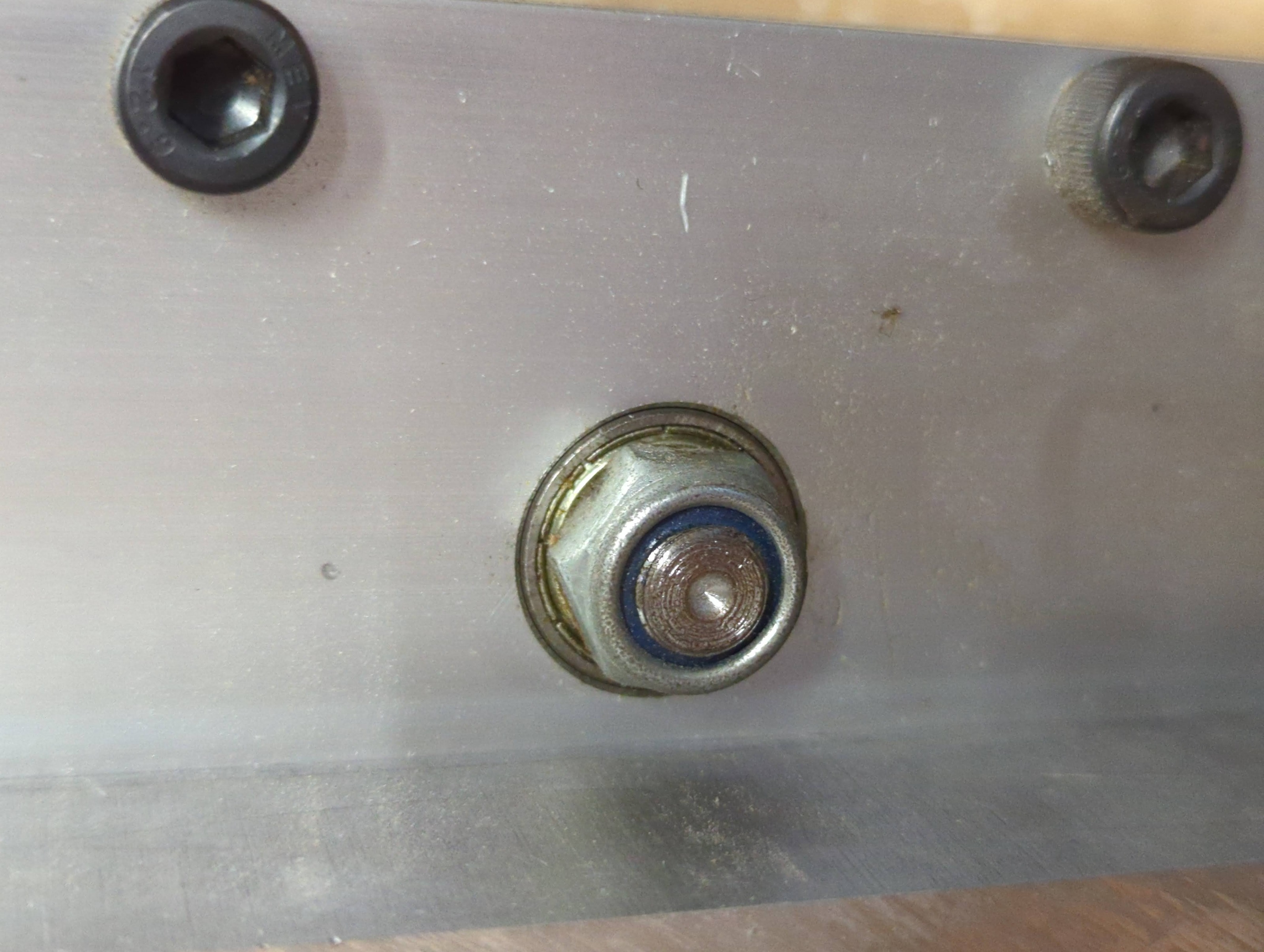
Attached image is the X axis ball screw bearing block. When it's not under the load, only screw/nut is spinning based on movement, but once it starts cutting, the inner bearing block itself spins together from time to time. Also I can see the bearing block wiggles within the bearing pocket. In other words, there is play in bearing and bearing pocket which will wiggle under the load. I suspect this is the source of backlash under the load.
Thing is, I don't know how to fix this.
First, how to unscrew this nut? Once put wrench and turn, it just make stepper motor attached on the other hand lose steps. I don't know how to hold the ball screw while unscrew this nut.
Assuming I unscrew the nut and removed the bearing from the pocket, how to set it in place? It's very thin gap.
I might redesign the whole Z plate but due to this wiggle, my hole cutting is always inaccurate and I'm not sure my new z plate has correct size for bearing to tightly fit.
Any insight would be appreciated.
Replied by merongi on topic Dimension accuracy loss under load
Meanwhile, I think I found the source of backlash under the load but I don't know how to fix.
Attached image is the X axis ball screw bearing block. When it's not under the load, only screw/nut is spinning based on movement, but once it starts cutting, the inner bearing block itself spins together from time to time. Also I can see the bearing block wiggles within the bearing pocket. In other words, there is play in bearing and bearing pocket which will wiggle under the load. I suspect this is the source of backlash under the load.
Thing is, I don't know how to fix this.
First, how to unscrew this nut? Once put wrench and turn, it just make stepper motor attached on the other hand lose steps. I don't know how to hold the ball screw while unscrew this nut.
Assuming I unscrew the nut and removed the bearing from the pocket, how to set it in place? It's very thin gap.
I might redesign the whole Z plate but due to this wiggle, my hole cutting is always inaccurate and I'm not sure my new z plate has correct size for bearing to tightly fit.
Any insight would be appreciated.
Attachments:
Last edit: 17 Mar 2024 06:01 by merongi.
Please Log in or Create an account to join the conversation.
Time to create page: 0.145 seconds