Dimension accuracy loss under load

More
2 years 8 months ago #293820 by merongi
It was runout issue. Last time I measured runout, it was <0.002" but this time it's like 0.006". Checked the collet and there was a chip. Once I remove it, it went down to 0.0015", which is ~0.038mm. It may still create 0.1mm dimensional error though, but not 0.2mm.
Thanks!
The following user(s) said Thank You: tommylight

Please Log in or Create an account to join the conversation.

More
2 years 8 months ago #293840 by besriworld
Usually, stepper motor drives make a similar defect.

Please Log in or Create an account to join the conversation.

More
2 years 8 months ago - 2 years 8 months ago #293845 by Mecanix
Excellent visuals. Runout or not, that infamous and consistent fish-scale effect left by the cutter on the surfaces indicate a severely out-of-tram Z. Start with a "how to tram your mill" tutorial, then once that's within spec move on to mapping linearity and accuracy of the screws with compensation files (see: wiki.linuxcnc.org/cgi-bin/wiki.pl?Screw_Compensation ).

That will take care of both your backlash and linearity/error. Done properly you should be able to mill a bore/boss within a 10~20um accuracy.
Last edit: 2 years 8 months ago by Mecanix.
The following user(s) said Thank You: merongi

Please Log in or Create an account to join the conversation.

More
2 years 7 months ago - 2 years 7 months ago #296106 by merongi
  I fixed Tram in Y axis with grub screw but X axis fix requires some modification of spindle holder, so it would take some time and will be done after current project.
Meanwhile, I think I found the source of backlash under the load but I don't know how to fix.

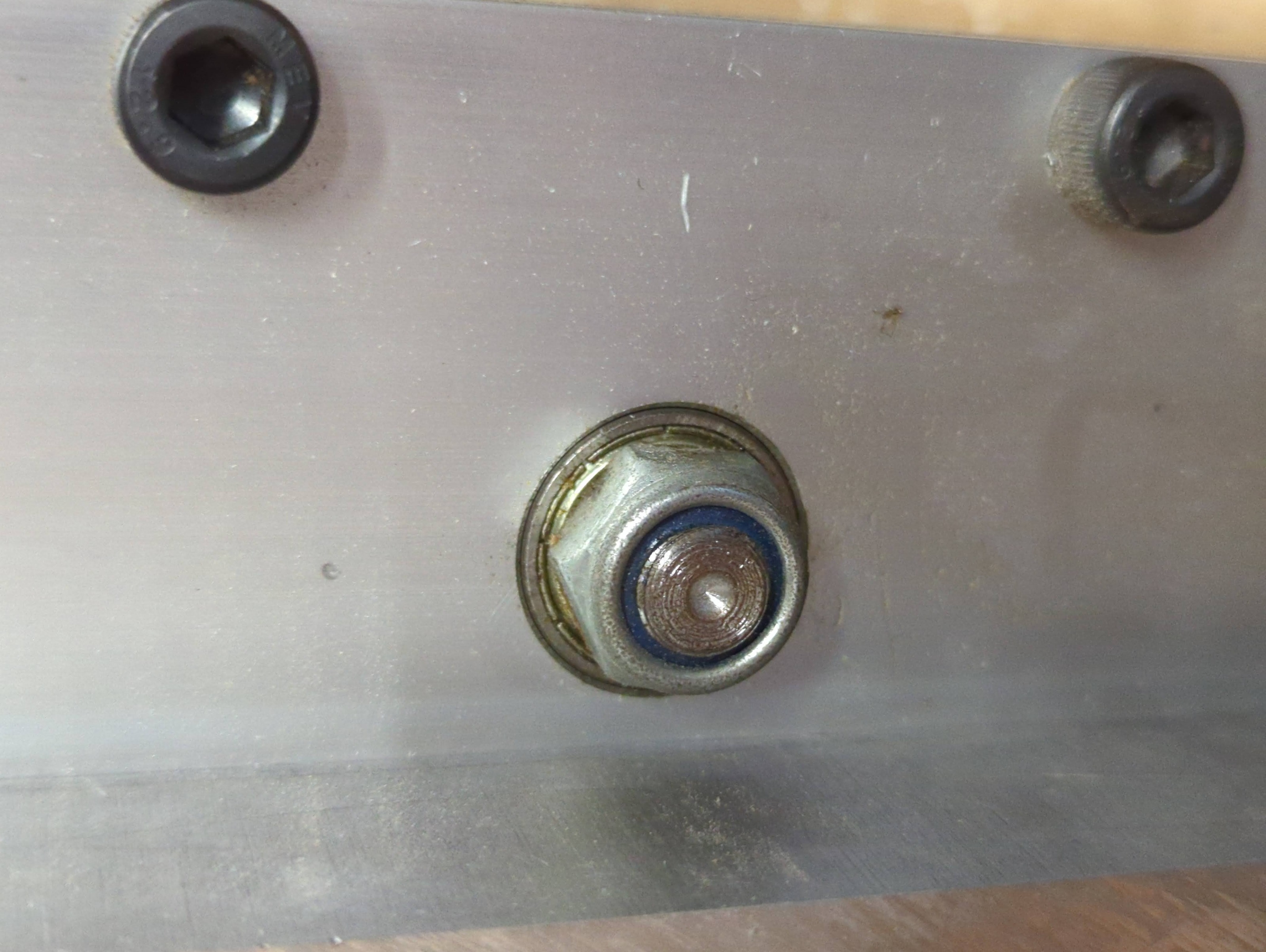
Attached image is the X axis ball screw bearing block. When it's not under the load, only screw/nut is spinning based on movement, but once it starts cutting, the inner bearing block itself spins together from time to time. Also I can see the bearing block wiggles within the bearing pocket. In other words, there is play in bearing and bearing pocket which will wiggle under the load. I suspect this is the source of backlash under the load.

Thing is, I don't know how to fix this.
First, how to unscrew this nut? Once put wrench and turn, it just make stepper motor attached on the other hand lose steps. I don't know how to hold the ball screw while unscrew this nut.
Assuming I unscrew the nut and removed the bearing from the pocket, how to set it in place? It's very thin gap.
I might redesign the whole Z plate but due to this wiggle, my hole cutting is always inaccurate and I'm not sure my new z plate has correct size for bearing to tightly fit.
Any insight would be appreciated.
Last edit: 2 years 7 months ago by merongi.

Please Log in or Create an account to join the conversation.

More
2 years 7 months ago - 2 years 7 months ago #296107 by tommylight
Axial bearing or angular roller bearing, what you have there is a simple radial bearing that is trying to hold axial loads.
Edit:
Maybe even a deep groove ball bearing would do, but mind the orientation.
Last edit: 2 years 7 months ago by tommylight. Reason: more info

Please Log in or Create an account to join the conversation.

More
2 years 7 months ago #296109 by Cant do this anymore bye all
A good setup would be like this:
Stepper Motor
Good quality coupler
Either a commercial bearing with 2 opposed angular contact bearings or a double row angular contact bearing with a method to lock the bearing in the housing on the outer ring. Do not rely on the bearing just being a tight fit. The screw is machined in such a way that it’s locked axially at this end.
This is the fixed end.
The other end is best achieved with a commercial “floating” bearing block, this allows the other end to move ever so slightly axially whilst contain fixing it radially. The end is usually turned to a smaller diameter than the fixed end and a circlip holds the bearing on the screw.

A couple of notes.
The cheaper fk or bk blocks use simple roller bearings these will give trouble, the more expensive ones will have 2 angular contact bearings fitting in an opposed setup.
The couplers can have an affect, the spiral type are basically useless under load as the will “wind up” introducing backlash.
Do not use the stepper motor alone on the driven end, as per many 3D printers, nor expect then to contain the end of a screw via a solid coupler.
If you have a look at some ball screw catalogues they have some very good diagrams, even if not using ball screws the same applies.
Unless you have a specific reason to I would avoid having both ends of the screw fixed, temperature increases or decreases will cause the screw and the machine to expand and contract and you want one end of the screw to be able to move.
I’ve seen quite a few badly implemented designs that cause trouble for the owners.
The following user(s) said Thank You: tommylight

Please Log in or Create an account to join the conversation.

Time to create page: 0.200 seconds
Powered by Kunena Forum