Bridgeport Boss5 stepper to servo
- Duc
- Offline
- Senior Member
-

Less
More
- Posts: 58
- Thank you received: 1
29 Nov 2015 20:40 #66035
by Duc
Bridgeport Boss5 stepper to servo was created by Duc
Backstory first
Few week ago I acquire a Bridgeport Boss 5 or 6 in a trade. Now the machine would move in the xyz axis using the stock control but I was unable to get the RS232 connection working for the machine. So I either had to use the teletypewriter to make punch tape or learn how to program line by line at the control panel. The teletypewriter was included with the machine.
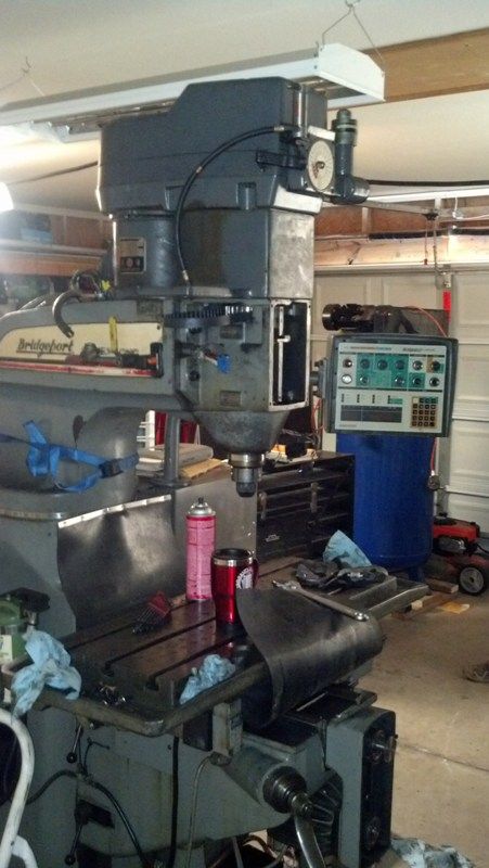
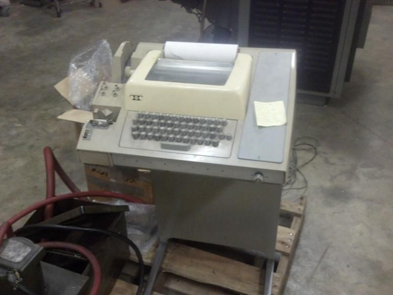
The teletypewriter is now in the back of the truck for a trip the scrap yard. Screw using that thing. New plan is to update the machine with mach3, gecko 203v drives, and Candcnc electronics. In time I may change to PMDX-126 board due to spindle control. The only board I need to buy for my CandCNC electronics is the MTA150 due to spare cards I had for my plasma table.
Please Log in or Create an account to join the conversation.
- Duc
- Offline
- Senior Member
-
Less
More
- Posts: 58
- Thank you received: 1
29 Nov 2015 20:41 #66036
by Duc
Replied by Duc on topic Bridgeport Boss5 stepper to servo
Plan
Candcnc electronics : UBOIII, TABLE I/O card, MTA150 drive card
Modify the Bridgeport Transformer to supply 70v using a full bridge rectifier and the caps removed from the Bridgeport.
Gecko 203V drives
Windows XP
1 Ghz computer w/ Parallel port
On to removing the old electronics. Took about a 5 hours to remove all the old stuff. Care was taken for the wiring and electronics, may need to buy less stuff later on.
Tape reader removed.
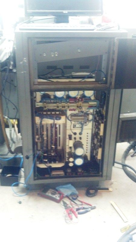
Caps removed. Will be saved for making the power supply.
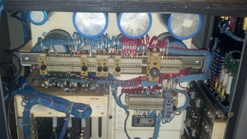
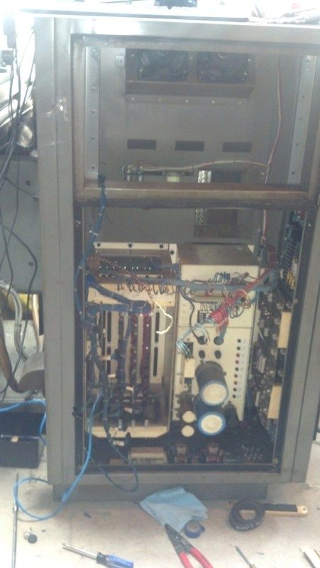
Power supply and card cage removed.
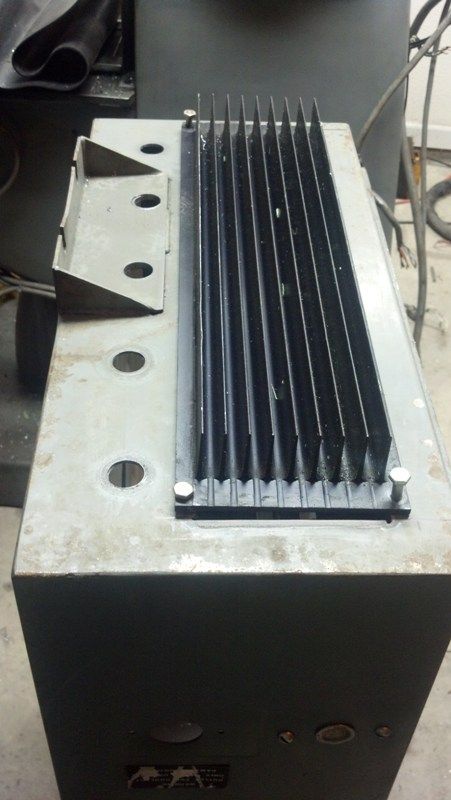
Massive heat sink was on the side panel on the electronics cabinet. I will be saving the heat sink. That stuff is pricey.

Please Log in or Create an account to join the conversation.
- Duc
- Offline
- Senior Member
-
Less
More
- Posts: 58
- Thank you received: 1
29 Nov 2015 20:44 #66037
by Duc
Replied by Duc on topic Bridgeport Boss5 stepper to servo
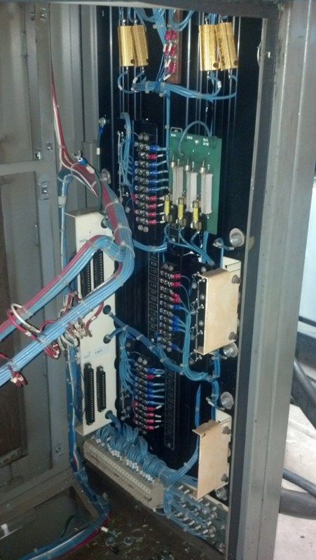
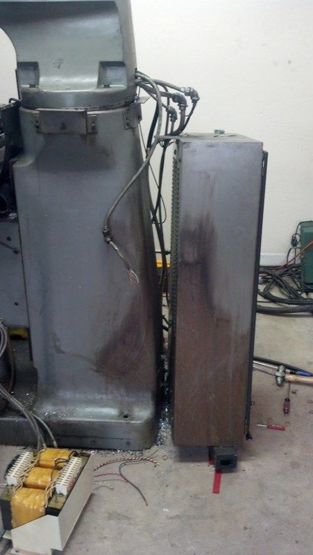
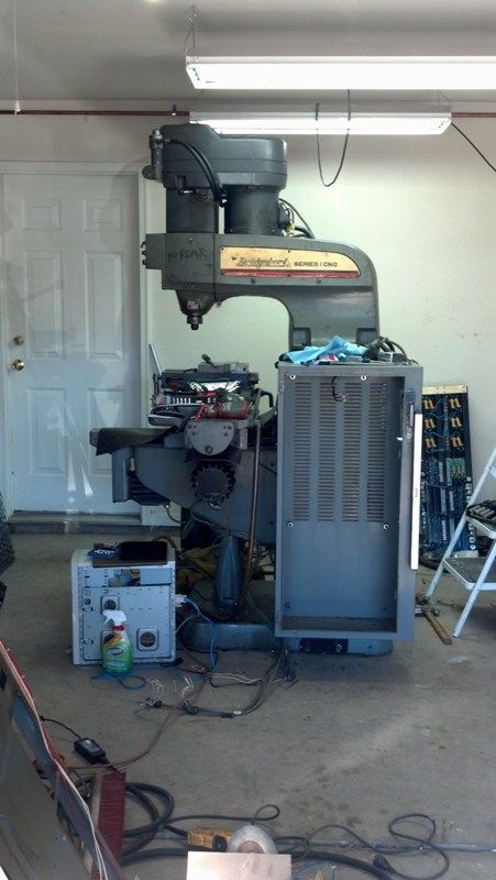
Side cabinet removed. The EMT conduit nuts caused a lot of swearing and smacking of the hammer. Never had a set refuse to unscrew like this set.
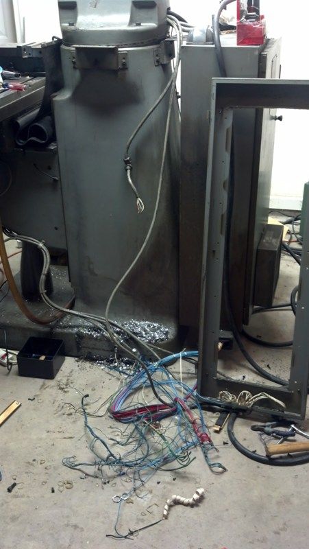
The teletype and side panel are already in the truck bed for a trip to the salvage yard tomorrow. The plan is to keep the power cabinet but move it to the side of the mill then insert all the electronics into the cabinet.

The teletype and side panel are already in the truck bed for a trip to the salvage yard tomorrow. The plan is to keep the power cabinet but move it to the side of the mill then insert all the electronics into the cabinet.
Please Log in or Create an account to join the conversation.
- Duc
- Offline
- Senior Member
-
Less
More
- Posts: 58
- Thank you received: 1
29 Nov 2015 20:44 #66038
by Duc
Replied by Duc on topic Bridgeport Boss5 stepper to servo
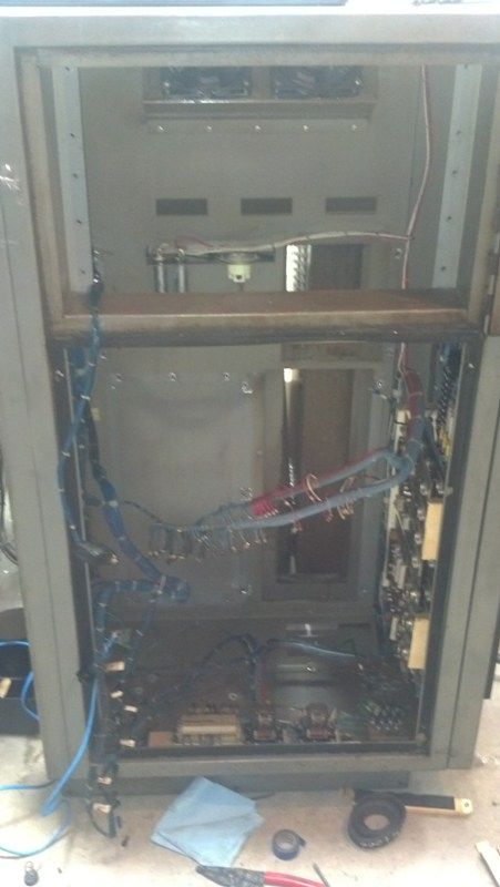
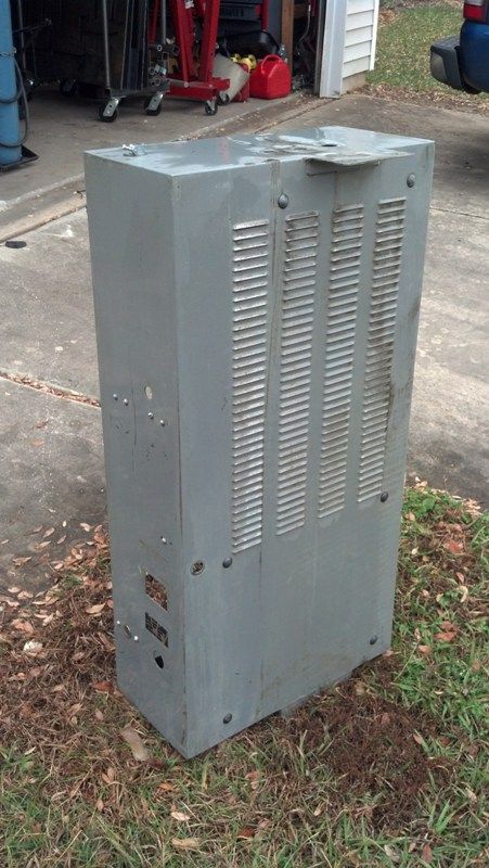
Rear cabinet removed.
30+ years of dirt and grime.
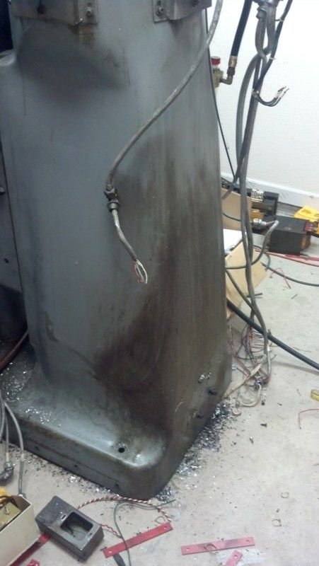
Cleaned
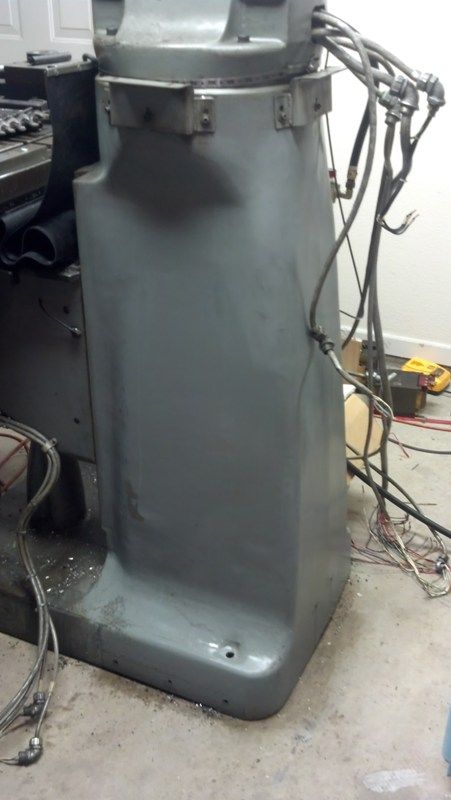
I attempted to clean the rear cabinet at a car wash bay. The grime refused to come off till I used Clorox cleaner. The Clorox cleaner worked magic on both the mill and the rear cabinet. Spray on and just wipe off.

30+ years of dirt and grime.

Cleaned

I attempted to clean the rear cabinet at a car wash bay. The grime refused to come off till I used Clorox cleaner. The Clorox cleaner worked magic on both the mill and the rear cabinet. Spray on and just wipe off.


Please Log in or Create an account to join the conversation.
- Duc
- Offline
- Senior Member
-
Less
More
- Posts: 58
- Thank you received: 1
29 Nov 2015 20:45 #66039
by Duc
By using a 3/8" thick plate for the adapter bracket, I was able to mount the panel dam near vertical and level. Owning a plasma table comes in handy sometimes. The bolt spread is wider on the bottom of the mill versus the cabinet. Bracket is about 7.5in wide by 6in tall.
Mounted up. Excuse the mess on the mill table.
I will be remounting the cleaned panel into the cabinet to use the disconnect and a place to mount the computer, gecko drives and Mill electronics. Next update in a day or two will include how the transformer was modified to output 75V and the circuit to smooth out the DC power.
Replied by Duc on topic Bridgeport Boss5 stepper to servo

By using a 3/8" thick plate for the adapter bracket, I was able to mount the panel dam near vertical and level. Owning a plasma table comes in handy sometimes. The bolt spread is wider on the bottom of the mill versus the cabinet. Bracket is about 7.5in wide by 6in tall.

Mounted up. Excuse the mess on the mill table.

I will be remounting the cleaned panel into the cabinet to use the disconnect and a place to mount the computer, gecko drives and Mill electronics. Next update in a day or two will include how the transformer was modified to output 75V and the circuit to smooth out the DC power.
Please Log in or Create an account to join the conversation.
- Duc
- Offline
- Senior Member
-
Less
More
- Posts: 58
- Thank you received: 1
29 Nov 2015 20:45 #66040
by Duc
Replied by Duc on topic Bridgeport Boss5 stepper to servo
Disclaimer: Electricity is dangerous and can kill if mishandled. Modifying transformers and using capacitors can result in death or serious injury.
Made some progress on the power supply for the gecko drives. I was shooting for 75 volts DC but over trimmed the coils on the transformer.
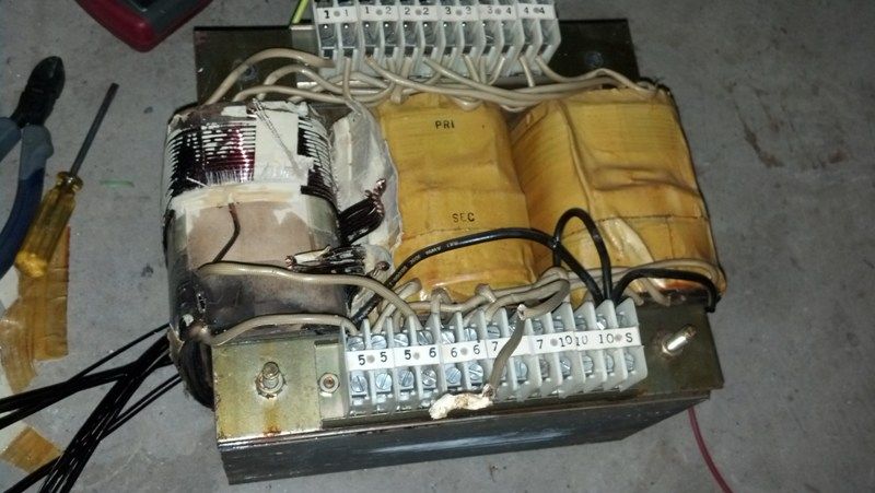
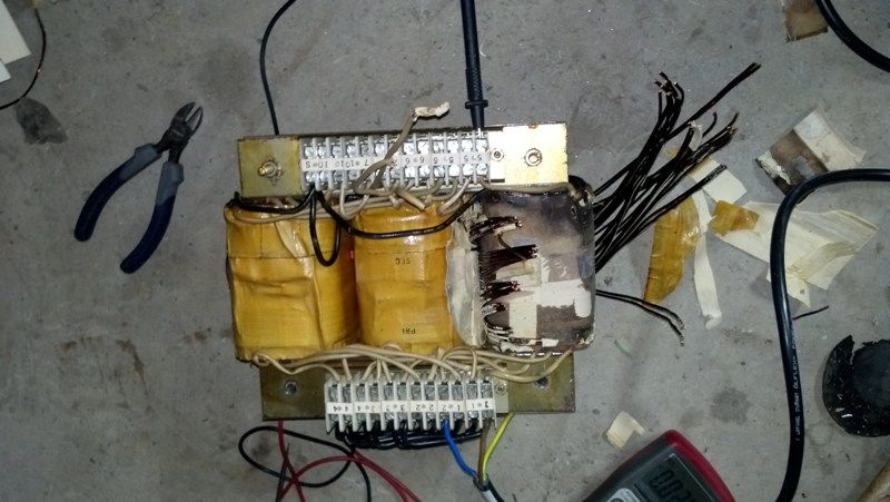
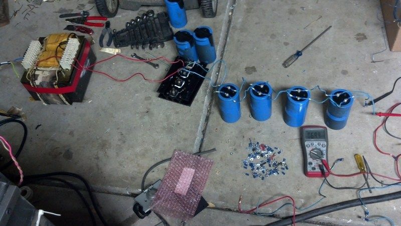
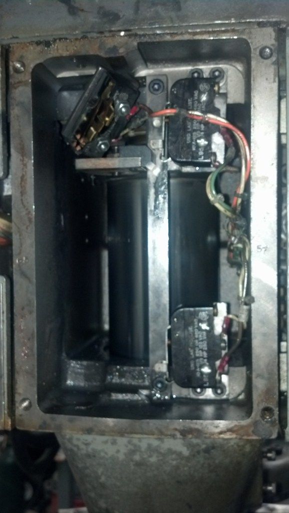
Testing of the power supply. About 70v Dc with very little AC ripple. Reused the Full-wave bridge rectifier, capacitors, and transformer from the Bridgeport to make the complete system. The system is missing a bleed down resistor for draining the capacitors when the system is off.
Made some progress on the power supply for the gecko drives. I was shooting for 75 volts DC but over trimmed the coils on the transformer.


Testing of the power supply. About 70v Dc with very little AC ripple. Reused the Full-wave bridge rectifier, capacitors, and transformer from the Bridgeport to make the complete system. The system is missing a bleed down resistor for draining the capacitors when the system is off.

Please Log in or Create an account to join the conversation.
- Duc
- Offline
- Senior Member
-
Less
More
- Posts: 58
- Thank you received: 1
29 Nov 2015 20:46 #66041
by Duc
The mill is a rigid ram model so the head doesn't tilt or rotate. Not to sure how much stuff I will hang off the edge of the mill due to this. I will need to move the cabinet back a couple of inches. The coolant drain on the rear of the table will currently hit the cabinet when moved to the rear limit.
My awesome cardboard layout for the machine. Total waste of space for the cabinet. Maybe in time I will invest more money into smaller components and a new cabinet.
Insetting the Gecko drive heat sink into the cabinet. Drilled the holes for the cables for the motors. For now I spaced the geckos about 2 inches apart then I realized I could have them side by side. To late due to the holes being drilled into the cabinet. I added a few extra holes for when I had a 4th axis or misc stuff.
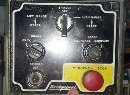
I will try to retain all the buttons of the front face for function.
Replied by Duc on topic Bridgeport Boss5 stepper to servo
The cabinet looks like it would get in the way mounted on the side like that. I have had to hang plenty of parts off the back side of the table and swing the head over to work on them.
The mill is a rigid ram model so the head doesn't tilt or rotate. Not to sure how much stuff I will hang off the edge of the mill due to this. I will need to move the cabinet back a couple of inches. The coolant drain on the rear of the table will currently hit the cabinet when moved to the rear limit.
My awesome cardboard layout for the machine. Total waste of space for the cabinet. Maybe in time I will invest more money into smaller components and a new cabinet.

Insetting the Gecko drive heat sink into the cabinet. Drilled the holes for the cables for the motors. For now I spaced the geckos about 2 inches apart then I realized I could have them side by side. To late due to the holes being drilled into the cabinet. I added a few extra holes for when I had a 4th axis or misc stuff.

I will try to retain all the buttons of the front face for function.

Please Log in or Create an account to join the conversation.
- Duc
- Offline
- Senior Member
-
Less
More
- Posts: 58
- Thank you received: 1
29 Nov 2015 20:46 #66042
by Duc
Replied by Duc on topic Bridgeport Boss5 stepper to servo
Work on the mill as been progressing really well.
First the rules that I had to follow for the build.
1. No buying parts unless I earned the money off the table per the GF. -Not really going to complain about this one. She is better with money than I am and it will cause me less stress. In no way do I make alot of money off the table but I do have a full time engineering job.
2. Still need to spend some time with her on the weekends. - Propane garage heater to the rescue. Garage is a palmy 70-75 degrees so she can read her book in the garage or chat with me.
Control system.
Here were the systems I was debating about for the control system. Rough pricing listed for anyone that is having the same issues
PDMX (can use linuxcnc or mach3) Limited I/O points
$174 PDMX-126 Breakout board
$57 PDMX-107 Isolated spindle control (controls VFD)
$200 Ethernet smoothstepper (Can be omitted) Way to avoid using the parallel port
$200 Mach3 License (Already own a copy for my plasma table.)
Mesa Card setup (Linuxcnc only)
5i25 PCI card
7i76 breakout board (controls 5 steppers, spindle encoder, isolated analog spindle speed control, 48 I/O points.)
$200 for plug-in-play setup.
I went with the mesa card setup for the massive amount of I/O points and the option to run 5 axis's from one card. Plus later on I may decide to add a encoder to the spindle to allow for rigid tapping. The PDMX can be expanded to that many I/O points with another card.
Linuxcnc can be a little scary at first but is fairly easy to get started with the new GUI setups that are included for the Mesa cards.
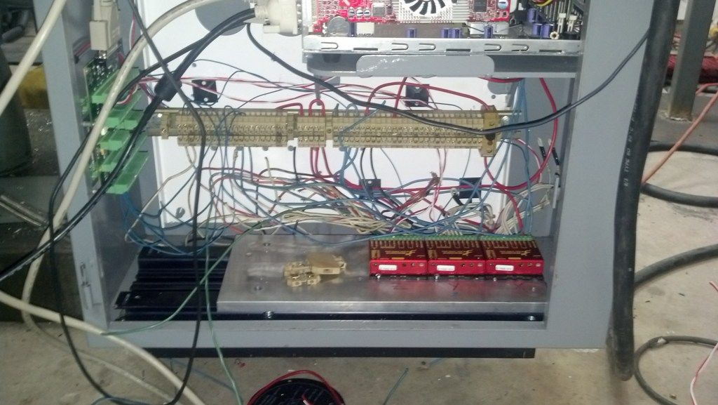
Geckos 203v mounted to a 1/2 slab of Aluminum which is bolted to one of the original heat seaks. The wiring is little bit of a mess at this time but should be cleaned up after this weekend. Later on I will mill a new slab that will include fins on the bottom for the geckos. Sounds like a good starter project.
The wiring TB's were pulled from the original wirig to save on costs. Also reused alot of the original wiring for connecting stuff. Tons of 20, 18, 14, 12ga wires. I would say this saved at least $100.
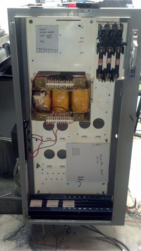
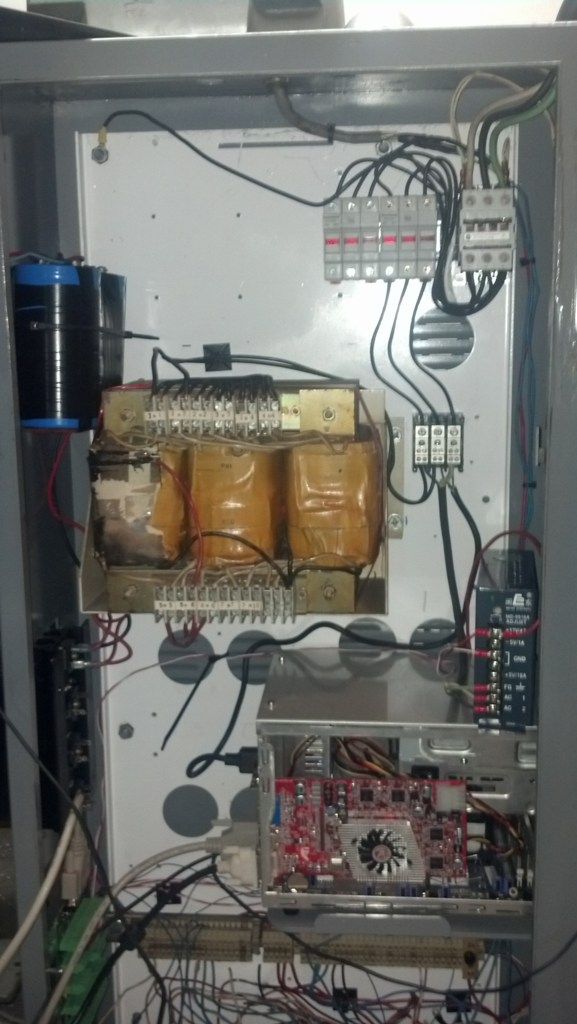
Cabinet
Top left space reserved for Hitachi WJ200-015LF VFD
Top right - Fuses and a 40amp contactor
Middle - Transformer for the 70volts dc and the caps are sitting off to the left. I will make a new shelf this weekend to mount the caps.
Computer is mounted to a custom made shelf. A shuttle PC fit in the cabinet really well. Computer is not fully setted on the shelf during pictures.
Z limits caused some issues. I was wiring the top switch as the home, middle as upper limit and bottom switch as lower limit. This was all fine and dandy till I screwed up the config for the Z travel and managed to crush the home switch. I forgot the Z has a -5.0in travel and not a positive +5.0in like I programed in the config. I was pissed that I needed to buy a new switch till I researched the switch in the manual and found it be not needed. In the original configuration of the Z switches, the 2 were limits and one was a deacceleration switch before it hit the top switch. With modern controls I dont need one of the switches. In linuxcnc I can set the top switch to home and a limit.
Sunday night I had the table and quill moving by computer. VFD should be on the way after this weekend if CL goes correct.
First the rules that I had to follow for the build.
1. No buying parts unless I earned the money off the table per the GF. -Not really going to complain about this one. She is better with money than I am and it will cause me less stress. In no way do I make alot of money off the table but I do have a full time engineering job.
2. Still need to spend some time with her on the weekends. - Propane garage heater to the rescue. Garage is a palmy 70-75 degrees so she can read her book in the garage or chat with me.
Control system.
Here were the systems I was debating about for the control system. Rough pricing listed for anyone that is having the same issues
PDMX (can use linuxcnc or mach3) Limited I/O points
$174 PDMX-126 Breakout board
$57 PDMX-107 Isolated spindle control (controls VFD)
$200 Ethernet smoothstepper (Can be omitted) Way to avoid using the parallel port
$200 Mach3 License (Already own a copy for my plasma table.)
Mesa Card setup (Linuxcnc only)
5i25 PCI card
7i76 breakout board (controls 5 steppers, spindle encoder, isolated analog spindle speed control, 48 I/O points.)
$200 for plug-in-play setup.
I went with the mesa card setup for the massive amount of I/O points and the option to run 5 axis's from one card. Plus later on I may decide to add a encoder to the spindle to allow for rigid tapping. The PDMX can be expanded to that many I/O points with another card.
Linuxcnc can be a little scary at first but is fairly easy to get started with the new GUI setups that are included for the Mesa cards.
Geckos 203v mounted to a 1/2 slab of Aluminum which is bolted to one of the original heat seaks. The wiring is little bit of a mess at this time but should be cleaned up after this weekend. Later on I will mill a new slab that will include fins on the bottom for the geckos. Sounds like a good starter project.
The wiring TB's were pulled from the original wirig to save on costs. Also reused alot of the original wiring for connecting stuff. Tons of 20, 18, 14, 12ga wires. I would say this saved at least $100.

Cabinet
Top left space reserved for Hitachi WJ200-015LF VFD
Top right - Fuses and a 40amp contactor
Middle - Transformer for the 70volts dc and the caps are sitting off to the left. I will make a new shelf this weekend to mount the caps.
Computer is mounted to a custom made shelf. A shuttle PC fit in the cabinet really well. Computer is not fully setted on the shelf during pictures.

Z limits caused some issues. I was wiring the top switch as the home, middle as upper limit and bottom switch as lower limit. This was all fine and dandy till I screwed up the config for the Z travel and managed to crush the home switch. I forgot the Z has a -5.0in travel and not a positive +5.0in like I programed in the config. I was pissed that I needed to buy a new switch till I researched the switch in the manual and found it be not needed. In the original configuration of the Z switches, the 2 were limits and one was a deacceleration switch before it hit the top switch. With modern controls I dont need one of the switches. In linuxcnc I can set the top switch to home and a limit.

Sunday night I had the table and quill moving by computer. VFD should be on the way after this weekend if CL goes correct.
Please Log in or Create an account to join the conversation.
- Duc
- Offline
- Senior Member
-
Less
More
- Posts: 58
- Thank you received: 1
29 Nov 2015 20:47 #66043
by Duc
Replied by Duc on topic Bridgeport Boss5 stepper to servo
Problem 1 X-axis turning off
Finally had to mount the drivers down solid and add heat sink compound. I believe this will solve the issue but awaiting a much longer test.
http://i1221.photobucket.com/albums/dd465/shefron/Machinery/Heatsinkcompound_zpsb8543ea1.jpg?t=1391286209
Problem 2 Noise while running spindle
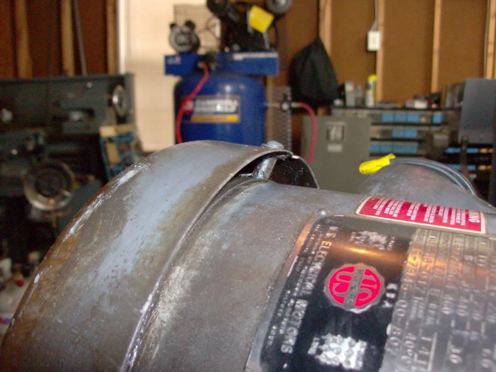
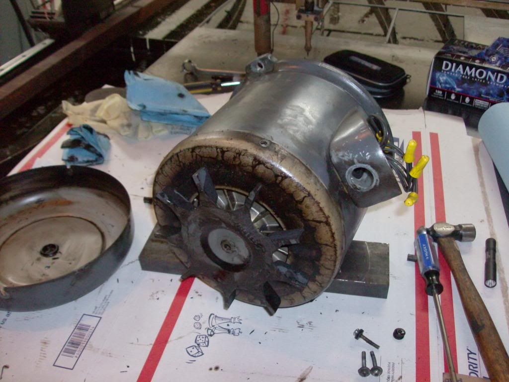
I had some fear that I needed to rebuild the spindle bearings till I torn down the top end for a single pulley conversion instead of the vari-drive system. I found the motor to be making the noise when I spun the shaft. Some how the motor fan shield was bent into the fan.
http://i1221.photobucket.com/albums/dd465/shefron/Machinery/Motorshieldbolt_zps83cbf8fe.jpg?t=1391286694
Might as well clean the motor up a bit and slot one of the mounting holes for adjusting belt tension when I use a single groove pulley system.
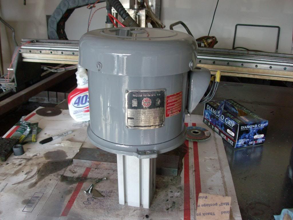
Slotted mounting hole
Finally had to mount the drivers down solid and add heat sink compound. I believe this will solve the issue but awaiting a much longer test.
http://i1221.photobucket.com/albums/dd465/shefron/Machinery/Heatsinkcompound_zpsb8543ea1.jpg?t=1391286209
Problem 2 Noise while running spindle
I had some fear that I needed to rebuild the spindle bearings till I torn down the top end for a single pulley conversion instead of the vari-drive system. I found the motor to be making the noise when I spun the shaft. Some how the motor fan shield was bent into the fan.
http://i1221.photobucket.com/albums/dd465/shefron/Machinery/Motorshieldbolt_zps83cbf8fe.jpg?t=1391286694
Might as well clean the motor up a bit and slot one of the mounting holes for adjusting belt tension when I use a single groove pulley system.
Slotted mounting hole
Please Log in or Create an account to join the conversation.
- Duc
- Offline
- Senior Member
-
Less
More
- Posts: 58
- Thank you received: 1
29 Nov 2015 20:48 #66044
by Duc
Replied by Duc on topic Bridgeport Boss5 stepper to servo
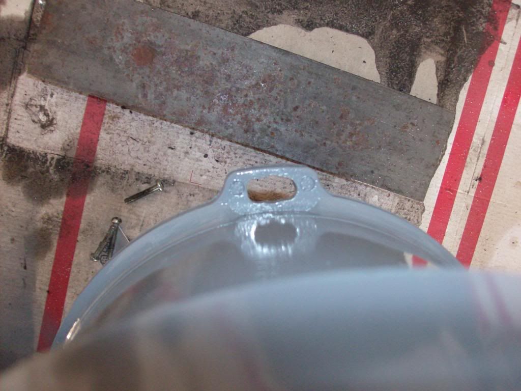
Problem 3 Vise mounting.
I will need to modify the coolant shield to allow the vise to mount along the Y-axis. Shouldn't be to hard but I need to cut some additional sheet metal. Somewhat a pain since I don't have a press brake.
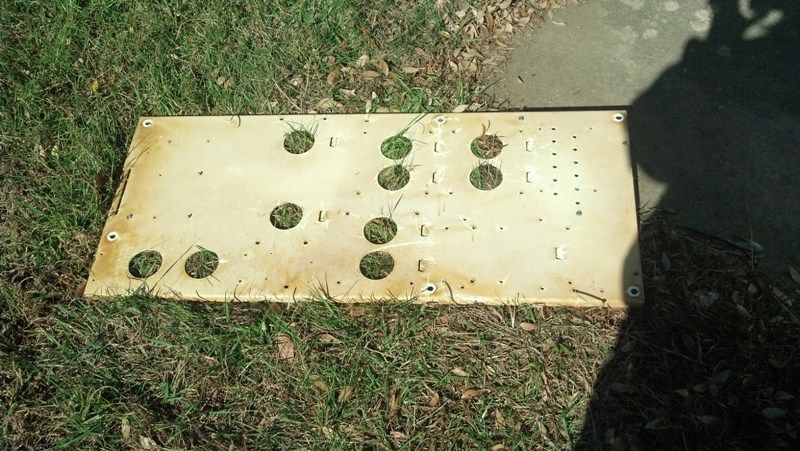
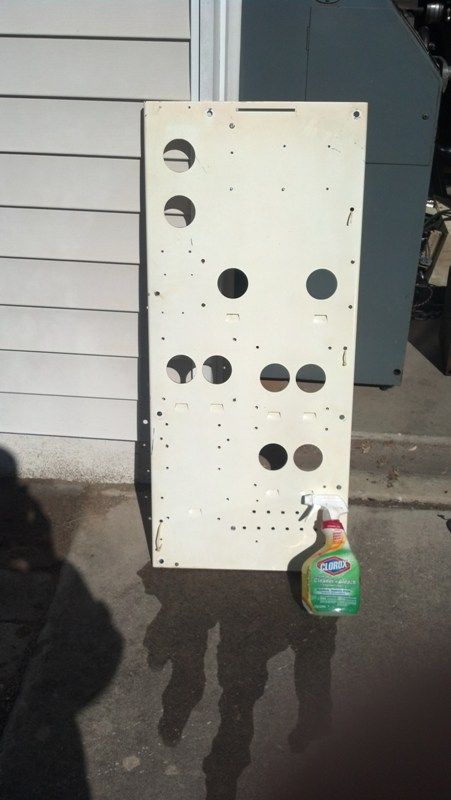
Also picked up another project for the mill once I get some more time. Cheap method for adding a MPG (manual pulse generator) and switches to control the mill. Only ran $160 dollars shipped from ebay. Later on I will design a cabinet that can swing out from the mill. The screen hole size is 8" wide by 6.5" tall. Overall panel size is 21.625" wide by 19.75" tall.
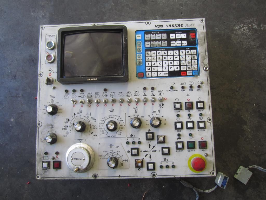
Will be easy to wire into the Mesa 7i76 I/O card. I am debating on ordering another 7i76 I/O card to mount into the cabinet then use serial comm to cut down on wiring. I will need to order a 7i73 pedant/ Control panel card to use the keypad with the setup.
http://i1221.photobucket.com/albums/dd465/shefron/Millpanelrear_zpsac07d58e.jpg?t=1391287605
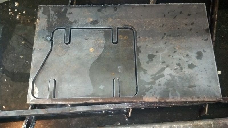
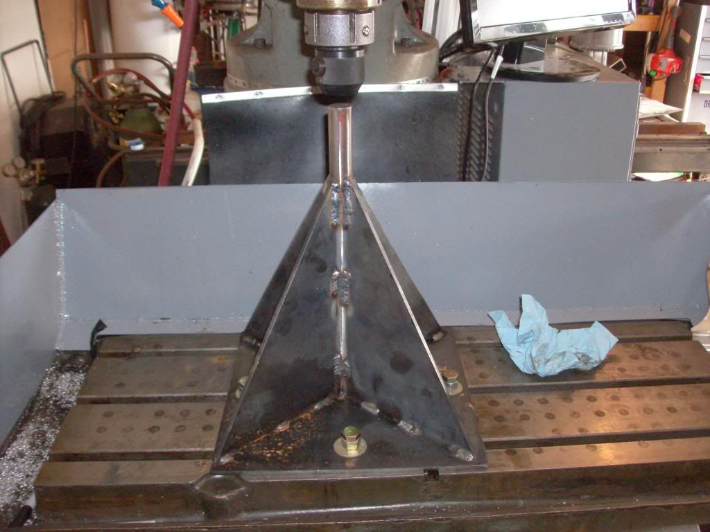
Fixture for moving the spindle assembly. My auction house friend had one of these during the move in of the machine. Not to hard to reproduce with the plasma table from 3/16" sheet metal and a 1 inch rod of steel. I've seen them on the web for 50 dollars I think but cant remember where I saw them. Just tighten rod into a tool holder before unbolting the spindle assembly. Works like a charm and later on I will be painting it.
I will need to modify the coolant shield to allow the vise to mount along the Y-axis. Shouldn't be to hard but I need to cut some additional sheet metal. Somewhat a pain since I don't have a press brake.
Also picked up another project for the mill once I get some more time. Cheap method for adding a MPG (manual pulse generator) and switches to control the mill. Only ran $160 dollars shipped from ebay. Later on I will design a cabinet that can swing out from the mill. The screen hole size is 8" wide by 6.5" tall. Overall panel size is 21.625" wide by 19.75" tall.
Will be easy to wire into the Mesa 7i76 I/O card. I am debating on ordering another 7i76 I/O card to mount into the cabinet then use serial comm to cut down on wiring. I will need to order a 7i73 pedant/ Control panel card to use the keypad with the setup.
http://i1221.photobucket.com/albums/dd465/shefron/Millpanelrear_zpsac07d58e.jpg?t=1391287605
Fixture for moving the spindle assembly. My auction house friend had one of these during the move in of the machine. Not to hard to reproduce with the plasma table from 3/16" sheet metal and a 1 inch rod of steel. I've seen them on the web for 50 dollars I think but cant remember where I saw them. Just tighten rod into a tool holder before unbolting the spindle assembly. Works like a charm and later on I will be painting it.
Please Log in or Create an account to join the conversation.
Moderators: piasdom
Time to create page: 0.495 seconds