Retrofitting a 1986 Maho MH400E
- RotarySMP
-
 Topic Author
- Offline
- Platinum Member
-

Less
More
- Posts: 1633
- Thank you received: 595
26 Jul 2018 10:37 #114865
by RotarySMP
Replied by RotarySMP on topic Retrofitting a 1986 Maho MH400E
Bob, that looks like an excellent score. That K&O looks very similar to my friends TOS BN-102 , which replaced the Clarkson he sold to me. T&C grinders are an excellent time waster. You can produce extremely accurate swarf with them, so small it looks like dust.
Unfortunately the slotting head and overarm have no tooling. I haven't got them home yet, as a relative of my wife lives two blocks from the seller in Tirol, and picked it up for me. His daughter studies in Vienna, so he will deliver it to me when he next comes this way. Saves me eight hours of driving.
I have a little taiwanese made 6" rotary table, and have visions of a CNC rotary table for the MAHO, but so far my six pack of self medication have kept the visions under control. I like the way you through out that little tidbit about a magical Müllernick rotary table for me to now obsessively comb the internet for")
I say Andy Pugh's Holbrook blog thread (excellent work) and the video of the cycloidal rotary table design, but didn't know it had been made.
Mark
Unfortunately the slotting head and overarm have no tooling. I haven't got them home yet, as a relative of my wife lives two blocks from the seller in Tirol, and picked it up for me. His daughter studies in Vienna, so he will deliver it to me when he next comes this way. Saves me eight hours of driving.
I have a little taiwanese made 6" rotary table, and have visions of a CNC rotary table for the MAHO, but so far my six pack of self medication have kept the visions under control. I like the way you through out that little tidbit about a magical Müllernick rotary table for me to now obsessively comb the internet for
I say Andy Pugh's Holbrook blog thread (excellent work) and the video of the cycloidal rotary table design, but didn't know it had been made.
Mark
Please Log in or Create an account to join the conversation.
- andypugh
-

- Offline
- Moderator
-

Less
More
- Posts: 19879
- Thank you received: 4644
26 Jul 2018 11:12 #114867
by andypugh
You probably don't need a rotary table on a CNC mill as you can generally get the same effect with coordinated motion.
But an A-axis is likely to be useful for some jobs.
I think that this is the A-axis that Bob is referring to. (It isn't based on the cycloidal design but on a commercial harmonic drive)
Replied by andypugh on topic Retrofitting a 1986 Maho MH400E
I have a little taiwanese made 6" rotary table, and have visions of a CNC rotary table for the MAHO,
You probably don't need a rotary table on a CNC mill as you can generally get the same effect with coordinated motion.
But an A-axis is likely to be useful for some jobs.
I think that this is the A-axis that Bob is referring to. (It isn't based on the cycloidal design but on a commercial harmonic drive)
Please Log in or Create an account to join the conversation.
- RotarySMP
-
Topic Author
- Offline
- Platinum Member
-
Less
More
- Posts: 1633
- Thank you received: 595
26 Jul 2018 14:26 #114883
by RotarySMP
Replied by RotarySMP on topic Retrofitting a 1986 Maho MH400E
I was also thinking that you only really need the A axis on a CNC mill. I like the use of a harmonic drive by Brainright:
But you have taken that to a new level. With D1-4 interface...respect! How did you guage the nose taper? The ISO 702-2 standard for that taper results in a +/- tolerance of under a 0.01mm.
Did you finish that project? The Blog ends with you contemplating the motor and LinuxCNC integration.
Mark
But you have taken that to a new level. With D1-4 interface...respect! How did you guage the nose taper? The ISO 702-2 standard for that taper results in a +/- tolerance of under a 0.01mm.
Did you finish that project? The Blog ends with you contemplating the motor and LinuxCNC integration.
Mark
Please Log in or Create an account to join the conversation.
- andypugh
-
- Offline
- Moderator
-
Less
More
- Posts: 19879
- Thank you received: 4644
26 Jul 2018 14:37 #114884
by andypugh
It needs a little bit more work, but is basically there. The D1-4 adaptor came back from hardening the weekend before last and the servo drive and connectors are in place and configured. I am using an STMBL drive.
I need to fit the cams and make a riser block for the tailstock, and then it is ready to use. (In fact I can use it now, but without a tailstock and the cams fall out when the chuck is removed)
I used my existing chucks to judge the taper size, it's pretty easy to shave off 0.005 mm with a CNC lathe. (and if you over shoot then there is the option to re-cut the face, as the cam mounting holes are not in place at that point)
Replied by andypugh on topic Retrofitting a 1986 Maho MH400E
Did you finish that project? The Blog ends with you contemplating the motor and LinuxCNC integration.
Mark
It needs a little bit more work, but is basically there. The D1-4 adaptor came back from hardening the weekend before last and the servo drive and connectors are in place and configured. I am using an STMBL drive.
I need to fit the cams and make a riser block for the tailstock, and then it is ready to use. (In fact I can use it now, but without a tailstock and the cams fall out when the chuck is removed)
I used my existing chucks to judge the taper size, it's pretty easy to shave off 0.005 mm with a CNC lathe. (and if you over shoot then there is the option to re-cut the face, as the cam mounting holes are not in place at that point)
Please Log in or Create an account to join the conversation.
- RotarySMP
-
Topic Author
- Offline
- Platinum Member
-
Less
More
- Posts: 1633
- Thank you received: 595
29 Jul 2018 08:23 #115046
by RotarySMP
Replied by RotarySMP on topic Retrofitting a 1986 Maho MH400E
Yesterday I finished wiring up the buttons. Ended up with a bit of a ratsnest in the middle, and still need to test that all the circuits are correct.
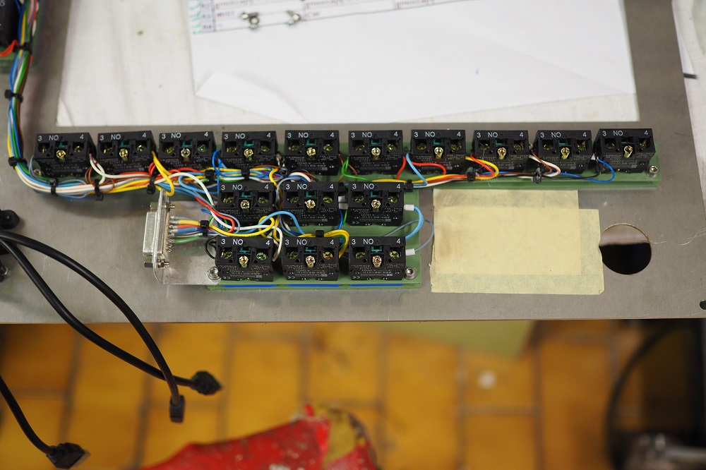
Next step is installing and wiring the two PEC-15 encoders on the user module, which will be Feedoverride, and maybe spindle speed override, or rapid override. I am pretty sceptical of implementing speed override, as having the machine pause, and change gear in the middle of a cut sounds like a recipe for scrap to me.
Mark
Please Log in or Create an account to join the conversation.
- andypugh
-
- Offline
- Moderator
-
Less
More
- Posts: 19879
- Thank you received: 4644
29 Jul 2018 12:58 #115057
by andypugh
I have considered this with my lathe, and at the moment it will never change gear while the spindle is on.
But I have considered modifying my gear box handler to know how to drop in to neutral, synchronise the input any output and carry on, but only during a G0 move. (when the tool will not be touching the work)
Replied by andypugh on topic Retrofitting a 1986 Maho MH400E
I am pretty sceptical of implementing speed override, as having the machine pause, and change gear in the middle of a cut sounds like a recipe for scrap to me.
I have considered this with my lathe, and at the moment it will never change gear while the spindle is on.
But I have considered modifying my gear box handler to know how to drop in to neutral, synchronise the input any output and carry on, but only during a G0 move. (when the tool will not be touching the work)
Please Log in or Create an account to join the conversation.
- RotarySMP
-
Topic Author
- Offline
- Platinum Member
-
Less
More
- Posts: 1633
- Thank you received: 595
29 Jul 2018 13:04 #115058
by RotarySMP
Replied by RotarySMP on topic Retrofitting a 1986 Maho MH400E
I would love to see some current videos of your lathe in use Andy. You made an incredible job of it, but like mostretrofit's, once it is up in running, the audiance doesn't lose interest.
Is spindle speed override used to compensate for too conservative assumptions in the CAM tool path generation, or more used to alter frequencies to prevent chatterdue to harmonics?
Mark
Is spindle speed override used to compensate for too conservative assumptions in the CAM tool path generation, or more used to alter frequencies to prevent chatterdue to harmonics?
Mark
Please Log in or Create an account to join the conversation.
- andypugh
-
- Offline
- Moderator
-
Less
More
- Posts: 19879
- Thank you received: 4644
29 Jul 2018 13:34 - 29 Jul 2018 15:35 #115059
by andypugh
Both of those, with a mill. Sometimes you might use it to improve the surface finish or to promote chip-breaking with a lathe.
It might be more useful on a lathe than with a mill.
With a mill I think you might want the ability to change spindle speed, but there is probably no need to change gear. (With a lathe using CSS you might easily be at 200 rpm on the OD then want 1200 rpm at the finish diameter)
Replied by andypugh on topic Retrofitting a 1986 Maho MH400E
Is spindle speed override used to compensate for too conservative assumptions in the CAM tool path generation, or more used to alter frequencies to prevent chatterdue to harmonics?
Both of those, with a mill. Sometimes you might use it to improve the surface finish or to promote chip-breaking with a lathe.
It might be more useful on a lathe than with a mill.
With a mill I think you might want the ability to change spindle speed, but there is probably no need to change gear. (With a lathe using CSS you might easily be at 200 rpm on the OD then want 1200 rpm at the finish diameter)
Last edit: 29 Jul 2018 15:35 by andypugh.
Please Log in or Create an account to join the conversation.
- RotarySMP
-
Topic Author
- Offline
- Platinum Member
-
Less
More
- Posts: 1633
- Thank you received: 595
30 Jul 2018 20:07 #115169
by RotarySMP
Replied by RotarySMP on topic Retrofitting a 1986 Maho MH400E
Considering I designed it, this control panel is going together quite well.
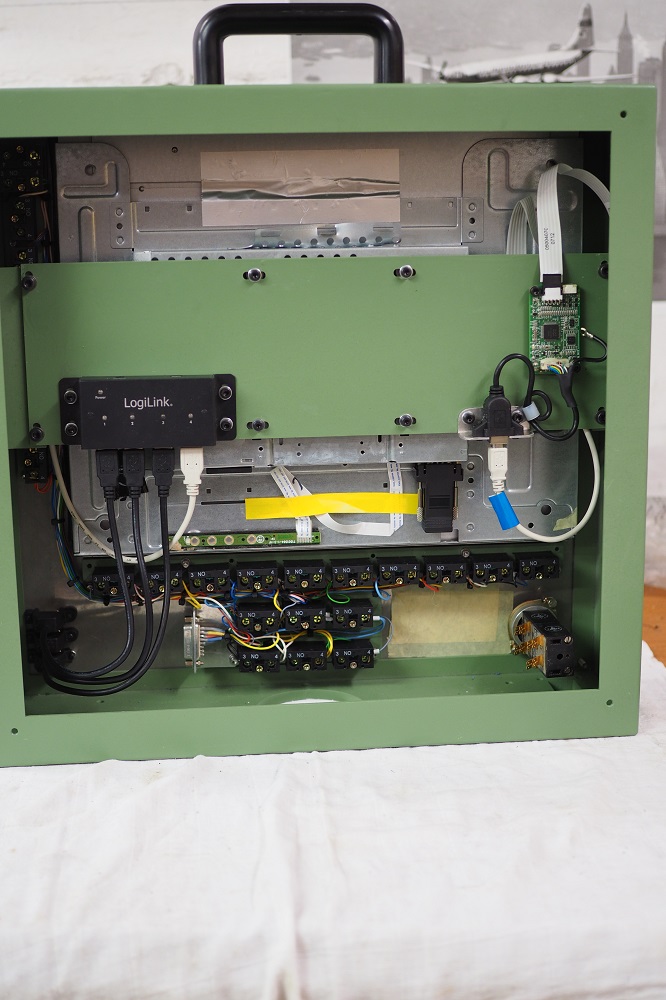
Normally by now I would have discovered that assembly requires a cyclotron to provide the strong magnetic field to levitate the critical screw while six, highly dextrous, infant hands similtaneously assembled everything else around it. Hope I am not dooming myself with premature optimism.
Mark
Normally by now I would have discovered that assembly requires a cyclotron to provide the strong magnetic field to levitate the critical screw while six, highly dextrous, infant hands similtaneously assembled everything else around it. Hope I am not dooming myself with premature optimism.
Mark
The following user(s) said Thank You: J Green
Please Log in or Create an account to join the conversation.
- J Green
- Offline
- Elite Member
-

Less
More
- Posts: 164
- Thank you received: 24
31 Jul 2018 21:26 - 31 Jul 2018 21:34 #115261
by J Green
Replied by J Green on topic Retrofitting a 1986 Maho MH400E
Mark Thank you for more Maho progress reports. The control panel seems to be in the final build stage .
The You-Tube video I was thinking about ( Generative gear cutting with a very simple tool (on a CNC with EMC2) ) started with a Walter T&C to grind a gear cutting tool and also showed Mr. Mueller using his reworked rotary axis. As I remember it , his rotary axis rework involved changing the bearings plus adding a encoder ( Heidenhain ROD 270 ? ) and a servo motor. The ROD 270 encoder was used by Maho on their manual and cnc rotary tables and they claimed the B axis resolution to be .001 Deg. I have seen MH400x machines having a cnc B axis rotary table vers a straight fixed table and thought you might keep a eye out for a rotary table.
Did read about Andy Pugh building his rotary axis and also his like for resolvers vers digital encoders. My thought is, if making a rotary axis now then what Andy has done could be less time and money for at least equal results . Can a resolver do .001Deg resolution ?
Mr Mueller had a second gear video ( no Walter T&C ) showing him making spiral gears ( Generative gear cutting with a less simple tool ). Mr Mueller may be back on You-Tube again! Yeah !
All right --break time is over - get back to the Retrofitting an more progress reports:
Bob
Last edit: 31 Jul 2018 21:34 by J Green. Reason: Tried to change a P to a smiley face
Please Log in or Create an account to join the conversation.
Moderators: piasdom
Time to create page: 0.613 seconds