Retrofitting a 1986 Maho MH400E
- RotarySMP
-
 Topic Author
- Offline
- Platinum Member
-

- Posts: 1540
- Thank you received: 572
If we need to go to the right position then the motor must turn right no matter what is the current position, if we need to go to the left position than the motor must turn left no mater what is the current position. But if we need to go to the middle position than the current position will determine the direction the motor must turn. This is what the left-middle cam tells to the controller, if the left-middle is on then the motor must turn right, else turn left. The others three cams are for stopping the motor once the position is reached. And the last cam, the one that is not connected to the controller is for slowing down the moto if we need to go the middle position so the motor will not overshoot.
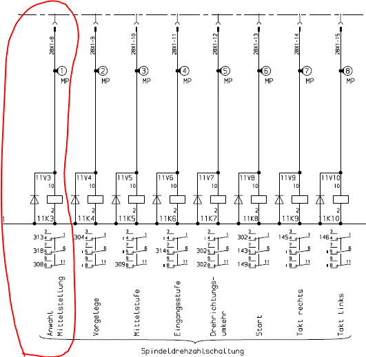
Sorry, my question wasn't clear. I understand the LH-MID cam for the feedback of which direction it needs to turn, and thus whether you need to energise the 11K7 reverse direction relay. What I don't get is the function of the 11K3 relay "select mid position"
The controller does not care if you have commanded 90 rpm and the true speed is 100 rpm, it will continue doing its job. I don’t think that 10% off in the spindle rpm is much of a deal, but you can always fine tune the feed rate to match the spindle speed.
Thanks for confirming that. How is your 600E conversion coming along. I haven't seen any photos of it lately (please post some).
Mark
Please Log in or Create an account to join the conversation.
- RotarySMP
-
 Topic Author
- Offline
- Platinum Member
-

- Posts: 1540
- Thank you received: 572
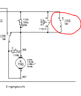
11K3 is the "Select mid position" relay. It is controlled by the controller. (see last post for schematic).
11K3 is normally closed, so the motor speed reduction variable resister 11R3 is normally bypassed, resulting in full motor speed. For the motor to slow down, that relay needs to be energised by LinuxCNC. The speed reduction cam's switch 11S14 provides a parallel bypass path. For current t flow throw the resister, to reduce motor speed, both relay 11k3 has to be energised, and the cam has to open 11S14.
I found it weird that MAHO added that 11K3 relay, as the decelleration system would work mechanically, but then realised that it was added so that a move from LH to RH doesn't have to slow down as it passes the middle position.
Mark
Please Log in or Create an account to join the conversation.
- drimaropoylos
- Offline
- Elite Member
-

- Posts: 265
- Thank you received: 40
Please Log in or Create an account to join the conversation.
- drimaropoylos
- Offline
- Elite Member
-

- Posts: 265
- Thank you received: 40
I found it weird that MAHO added that 11K3 relay, as the decelleration system would work mechanically, but then realised that it was added so that a move from LH to RH doesn't have to slow down as it passes the middle position.
Mark
Yes this is exactly the logic behind the use of 11K3.
John
Please Log in or Create an account to join the conversation.
- RotarySMP
-
 Topic Author
- Offline
- Platinum Member
-

- Posts: 1540
- Thank you received: 572
I love Greece. We vacation their every summer. It was cooler in Naxos than in Vienna for the last few weeks
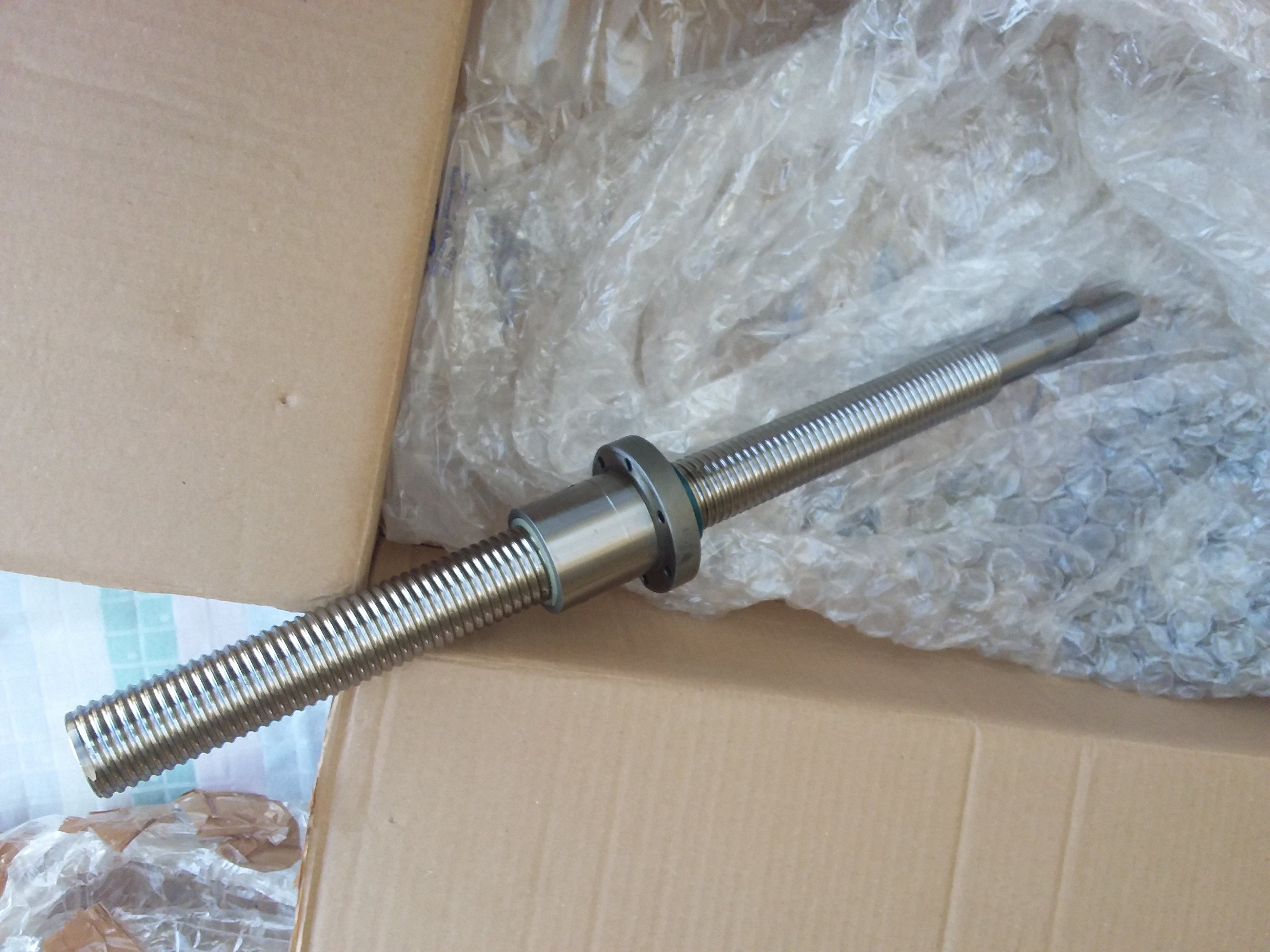
That ball screw looks new. When you install that pulley, could you please make some photos of it's component part, and how it is mounted/removed, as I couldn't find clear info on that, and I need to remove my X axis to get to the vertical glass scale encoder.
Thanks for confirming the 11K3 behavior.
In terms of gearbox timing, it is okay to set 11K7 "reverse direction" and also 11K4 (or 5 or 6) to power a motor in a single servo thread (1ms) ? Or would it be better to give it a few servo threads for the reverse relay to close and settle before putting on the power. If both are closed in a single servo thread, and if the motor relay closes faster, then the motor circuit will start to energise in one direction, and then the reverse relay will have to break that rising EMI of this inductive load, before reversing it, causing possible sparking of the contacts? Or is this not an a valid consideration with only 24VDC?
Mark
Please Log in or Create an account to join the conversation.
- drimaropoylos
- Offline
- Elite Member
-

- Posts: 265
- Thank you received: 40
John
Please Log in or Create an account to join the conversation.
- drimaropoylos
- Offline
- Elite Member
-

- Posts: 265
- Thank you received: 40
John
Please Log in or Create an account to join the conversation.
- RotarySMP
-
 Topic Author
- Offline
- Platinum Member
-

- Posts: 1540
- Thank you received: 572
I was looking at the spindle inhibit signals input to the control from hardware.
The spindle_Stopped signal on IPC1-23 I understand, as it's state is set by relay 1K7 through the tree of relays controlling the main spindle motor.
There is a second signal, "spindle_and _motion_stopped" signal on IPC1-24, which is set by the Lubriction unit (4A1). This makes no sense to me. Does anyone have any idea what this is about, and what the Phillips 432 used that signal for?
Mark
Please Log in or Create an account to join the conversation.
- cgroth
- Offline
- Junior Member
-

- Posts: 28
- Thank you received: 9
in my MAHO 300 manual it says "A pressure drop in the automativc lubrication system will operate a pressure switch in the main feed pipe thus switching off all feed and spindle drives". As far as I cut figure out, that pressure switch is wired through the pumps terminal.
In my case, the cabin door switches are wired in series.
Nowadays, I would always use a safety relais wired into the main safety circuit, e.g. a PNOZ or whatever is available. In my lathe, the lube-system is directly integrated in the safety circuit. I think there is no right or wrong. PRO: You get a direct feedback minimising the risk to ruin your bedways. CONTRA: If that happens during rough cutting you spoil your workpiece and presumably an expensive cutter without need.
Christian
Please Log in or Create an account to join the conversation.
- RotarySMP
-
 Topic Author
- Offline
- Platinum Member
-

- Posts: 1540
- Thank you received: 572
Mark
Please Log in or Create an account to join the conversation.


