Retrofitting a 1986 Maho MH400E
- Fermaq
- Offline
- Senior Member
-

Less
More
- Posts: 42
- Thank you received: 1
18 Nov 2018 23:04 - 18 Nov 2018 23:05 #120969
by Fermaq
Replied by Fermaq on topic Retrofitting a 1986 Maho MH400E
forum.linuxcnc.org/12-milling/33035-retr...aho-mh400e?start=170
I'm sorry if I'm going to bring up a last subject again. I'm starting now.
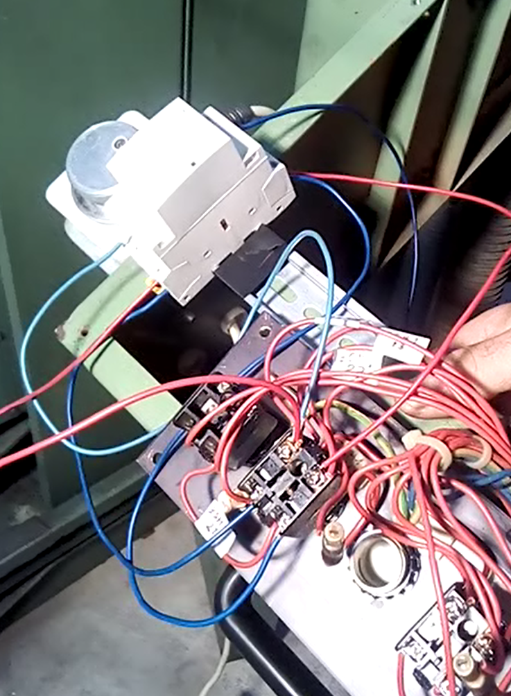
I read this page and others before, and after seeing that in my case the SH-1 has an open contact and a closed contact, I decided to put a small contactor that also had one open contact and one closed to "replace" the Clear with coil fed by a stage of his own, turned out to work, but I'm not sure if the method is appropriate, but resulted
I'm sorry if I'm going to bring up a last subject again. I'm starting now.
I read this page and others before, and after seeing that in my case the SH-1 has an open contact and a closed contact, I decided to put a small contactor that also had one open contact and one closed to "replace" the Clear with coil fed by a stage of his own, turned out to work, but I'm not sure if the method is appropriate, but resulted
Last edit: 18 Nov 2018 23:05 by Fermaq.
Please Log in or Create an account to join the conversation.
- RotarySMP
-
 Topic Author
- Offline
- Platinum Member
-

Less
More
- Posts: 1627
- Thank you received: 595
19 Nov 2018 13:36 - 19 Nov 2018 13:44 #120988
by RotarySMP
Replied by RotarySMP on topic Retrofitting a 1986 Maho MH400E
I do not expect to push more than one button at a time (except the top two during machine start, and I hard wired an extra contact onto the top button to deal with that).
I already measured through all the wiring when I assembled it, but guess I'll need to try and check it again, now it is installed vertical.
Mark
I already measured through all the wiring when I assembled it, but guess I'll need to try and check it again, now it is installed vertical.
Mark
Last edit: 19 Nov 2018 13:44 by RotarySMP.
Please Log in or Create an account to join the conversation.
- andypugh
-

- Offline
- Moderator
-

Less
More
- Posts: 19875
- Thank you received: 4642
19 Nov 2018 14:08 #120993
by andypugh
One quick thing to check, have you tried setting the "invert" parameter to zero? (It defaults to 1 as this is more usually what is needed).
If the input columns need positive voltage to be "true" then invert should be zero.
For reference the code is here:
github.com/LinuxCNC/linuxcnc/blob/master...nts/matrix_kb.c#L111
Though it isn't the clearest I have ever written.
Replied by andypugh on topic Retrofitting a 1986 Maho MH400E
I already measured through all the wiring when I assembled it, but guess I'll need to try and check it again, now it is installed vertical.
One quick thing to check, have you tried setting the "invert" parameter to zero? (It defaults to 1 as this is more usually what is needed).
If the input columns need positive voltage to be "true" then invert should be zero.
For reference the code is here:
github.com/LinuxCNC/linuxcnc/blob/master...nts/matrix_kb.c#L111
Though it isn't the clearest I have ever written.
The following user(s) said Thank You: RotarySMP
Please Log in or Create an account to join the conversation.
- RotarySMP
-
Topic Author
- Offline
- Platinum Member
-
Less
More
- Posts: 1627
- Thank you received: 595
19 Nov 2018 17:29 - 20 Nov 2018 07:42 #121014
by RotarySMP
Replied by RotarySMP on topic Retrofitting a 1986 Maho MH400E
Thanks Andy. I read the Matrix_kb manual entry lots of times, but never understood that bit.
I am struggling with the syntax here.
This doesn't work...
...putting it on it's one line, further down in the HAL before I started netting also doesn't work.
I'd appreciate a tip on how the syntax needs to be, please.
Mark
I am struggling with the syntax here.
This doesn't work...
loadrt matrix_kb config=5x5s names=maho_panel negative-logic=0...putting it on it's one line, further down in the HAL before I started netting also doesn't work.
maho_panel.negative-logic 0I'd appreciate a tip on how the syntax needs to be, please.
Mark
Last edit: 20 Nov 2018 07:42 by RotarySMP.
Please Log in or Create an account to join the conversation.
- andypugh
-
- Offline
- Moderator
-
Less
More
- Posts: 19875
- Thank you received: 4642
20 Nov 2018 14:06 #121053
by andypugh
Replied by andypugh on topic Retrofitting a 1986 Maho MH400E
setp maho_panel.negative-logic 0
The following user(s) said Thank You: RotarySMP
Please Log in or Create an account to join the conversation.
- RotarySMP
-
Topic Author
- Offline
- Platinum Member
-
Less
More
- Posts: 1627
- Thank you received: 595
20 Nov 2018 20:04 #121083
by RotarySMP
Replied by RotarySMP on topic Retrofitting a 1986 Maho MH400E
Thanks Andy, that solved the problem.
Mark
Mark
Please Log in or Create an account to join the conversation.
- andypugh
-
- Offline
- Moderator
-
Less
More
- Posts: 19875
- Thank you received: 4642
20 Nov 2018 20:29 #121086
by andypugh
That's a relief! I was worried that there was something really wrong with the component.
Replied by andypugh on topic Retrofitting a 1986 Maho MH400E
Thanks Andy, that solved the problem.
That's a relief! I was worried that there was something really wrong with the component.
Please Log in or Create an account to join the conversation.
- RotarySMP
-
Topic Author
- Offline
- Platinum Member
-
Less
More
- Posts: 1627
- Thank you received: 595
23 Nov 2018 09:40 - 23 Nov 2018 10:18 #121253
by RotarySMP
Replied by RotarySMP on topic Retrofitting a 1986 Maho MH400E
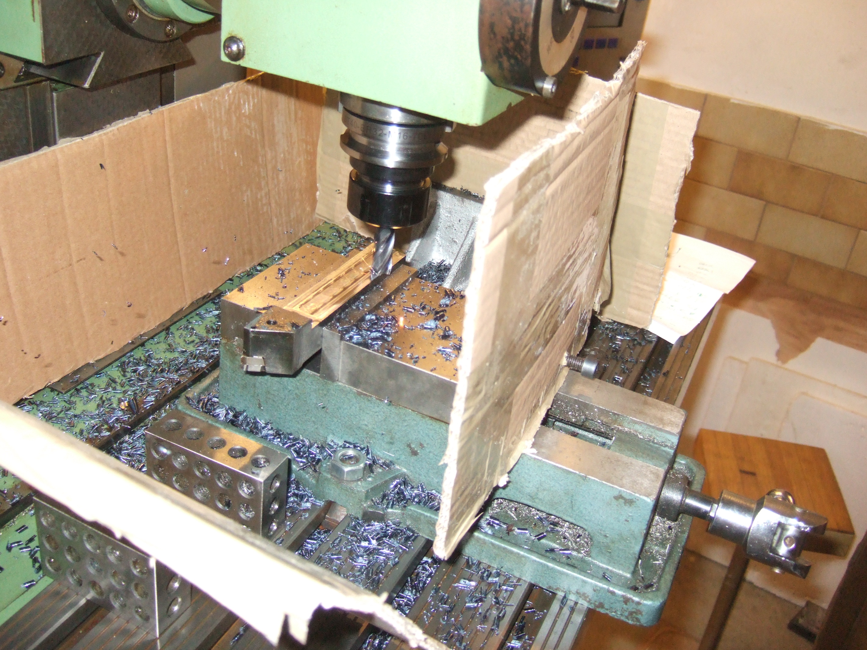
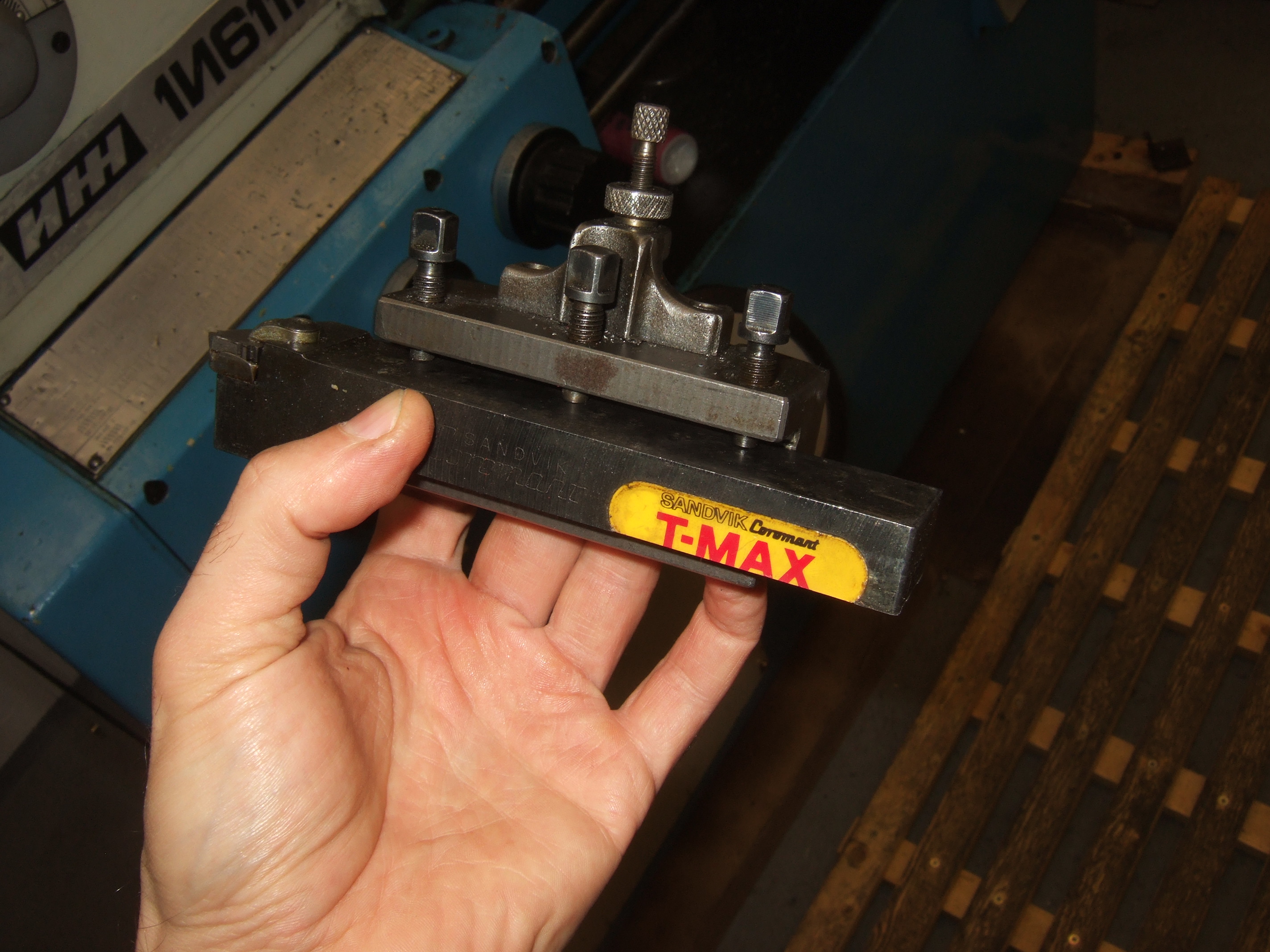
Sergey who programmed the gearbox comp for me, needed a couple of Sanvik 25x25mm insert lathe tool shanks milled down to 17mm to fit the multi-fix on his lathe.
Since I don't have the guards on, and can't use coolant, my long suffering 1/2" (12.7mm) four flute carbide end mill (bought at Boeing surplus a decade before I had the mill), was used. This mill is in pretty bad shape, from being misused as a counterbore on the lathe. It was already resharped by me on the Clarkson.
We did the first shank using a single layer program, and kept editing it and rerunning it for a lower Z. Actually the first pass, I wanted to try 0.5mm Ap, but screwed up typing and cut 5mm deep. Dumb mistake number 1. The MAHO chomped through like a champ though.
Once the first one was done, I cut/paste the code to make a gcode program to cut down the second shank in four passes.
This feeds and speed calculator feeds and speeds calculator[/url] was used, but I selected low carbon steel, rather than alloy steel. Dumb mistake number 2. Made for some fireworks, but the 1/2" (12.7mm) four flute carbide end mill was also a champ.
Unfortunately, I had an unwanted plunge cut in there. Dumb mistake number 3. This was obviously one mistake more than the mill would forgive, so the end mill gave up an edge, and is now back in the container of things needing resharpening. At least I got my stupidity on video. It seems stupidity on video is a big thing these days. I had used the LinuxCNC backplot to look for errors, and had clicked through the various views, but missed this.
Also picked up up a couple of other issues which will need to be addressed.
1/ When the spindle motor starts, the monitor sometimes blanks. I think it is a power interuption. Weird, as the original, unmodified MAHO power cable for the CRT monitor powers the LCD.
2/ The next job was to drill a 6 bolt holes for a chuck adaptor. Used a hole finder to set up pthe middle point. It turns out there is still some flakiness in the Y axis encoder. X-axis is correct, but as you can see, the scaling of the Y axis is out. It is not an INI scaling issue as the LS-403's have micron output from the EXE, and the INI is set at 1000.
Since this Y axis encoder was flakey in the past when its supply voltage was below 5V, and last week I'd wired the active USB Hub to be powered by that same little 5V PSU, that is where troubleshooting will start.
Mark
Last edit: 23 Nov 2018 10:18 by RotarySMP.
The following user(s) said Thank You: tommylight
Please Log in or Create an account to join the conversation.
- RotarySMP
-
Topic Author
- Offline
- Platinum Member
-
Less
More
- Posts: 1627
- Thank you received: 595
24 Nov 2018 20:19 - 24 Nov 2018 20:24 #121307
by RotarySMP
Replied by RotarySMP on topic Retrofitting a 1986 Maho MH400E
Since I think the last job was a little ambitious, today I took it easy. Just milled wrenching flats on all thread to make the mounting/adjusting studs for the isolator mounts which the MAHO is going to stand on. I set up the indexer* with a mag base as a stop.
I want to configure the two encoders mounted to the front panel.I need to change encoders= from 3 to 5 in the Loadrt section of the HAL, but can I configure the MESA to have the encoders 1-3 and 5,6 loading? I wired up the two additional encoders to those positions, as it fit the cable routing better.
When physical buttons are added which duplicate touch screen buttons in Gmoccapy, (e.g spindle on), do I need to use the or2 component to set up either the Gmoccapy button, or the physical button switching the output?
# --- Spindle on ---
loadrt or2
addf or2.0 servo-thread
#Input
net maho_panel.r0c4_sig-out maho_panel.key.r0c4 => or2.0.in0
net gmoccapy_[spindle.on buttont] => or2.0.in1
#output
net start-spindle or2.0.out motion.spindle-on
Is this the correct idea? Or is there an easier ways of doing this? How do I find gmoccapy's spindle on pin? Using HALSHOW there is none? I looked through the source code in github, but couldn't identify it.
Mark
* Cool tool, although whoever made it didn't have much of an eye for finishing. I was lucky to find it locally, as it takes the same 358E, W23 collets as my Boley 4LV lathe
Last edit: 24 Nov 2018 20:24 by RotarySMP.
Please Log in or Create an account to join the conversation.
- RotarySMP
-
Topic Author
- Offline
- Platinum Member
-
Less
More
- Posts: 1627
- Thank you received: 595
25 Nov 2018 19:42 #121336
by RotarySMP
Replied by RotarySMP on topic Retrofitting a 1986 Maho MH400E
Has anyone used OR2 ? Please take a look at the questions from yesterdays post, as I would appreciate a bit of help on this. At the moment i have the spindle physical buttons commented out. Also the additional encoders.
Today I needed to add further hole to turn a motor mount plate through 45°for the sand muller I am making. First time I've tried G83.
I need to find time to design the pendant housing, to learn to use CAM. Would be cool to machine a more complex part, but I am hoping that the X Bellows arrive before that, as it would be better to have flood coolant for that.
Mark
Please Log in or Create an account to join the conversation.
Moderators: piasdom
Time to create page: 0.404 seconds