Tree Kira VTC30 Retrofit
- chrisfischer
- Offline
- Senior Member
-

Less
More
- Posts: 44
- Thank you received: 10
20 Jun 2024 23:15 #303451
by chrisfischer
Tree Kira VTC30 Retrofit was created by chrisfischer
Hi guys. Im very excited to get a decent control in this new to me cnc mill from 1990.
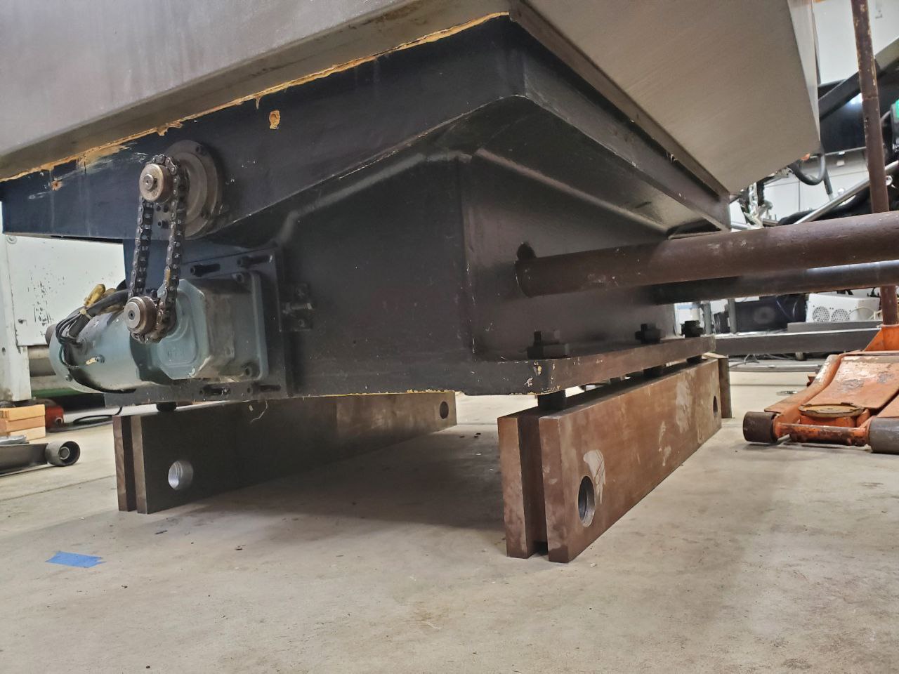
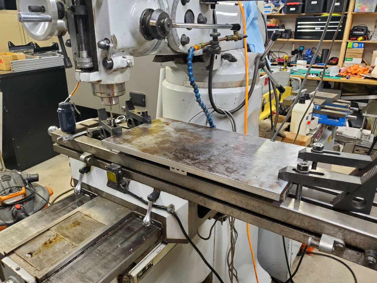
 The first thing I wanted to do is pick the machine up a little bit. It wasnt very ergonomic so low to the ground.
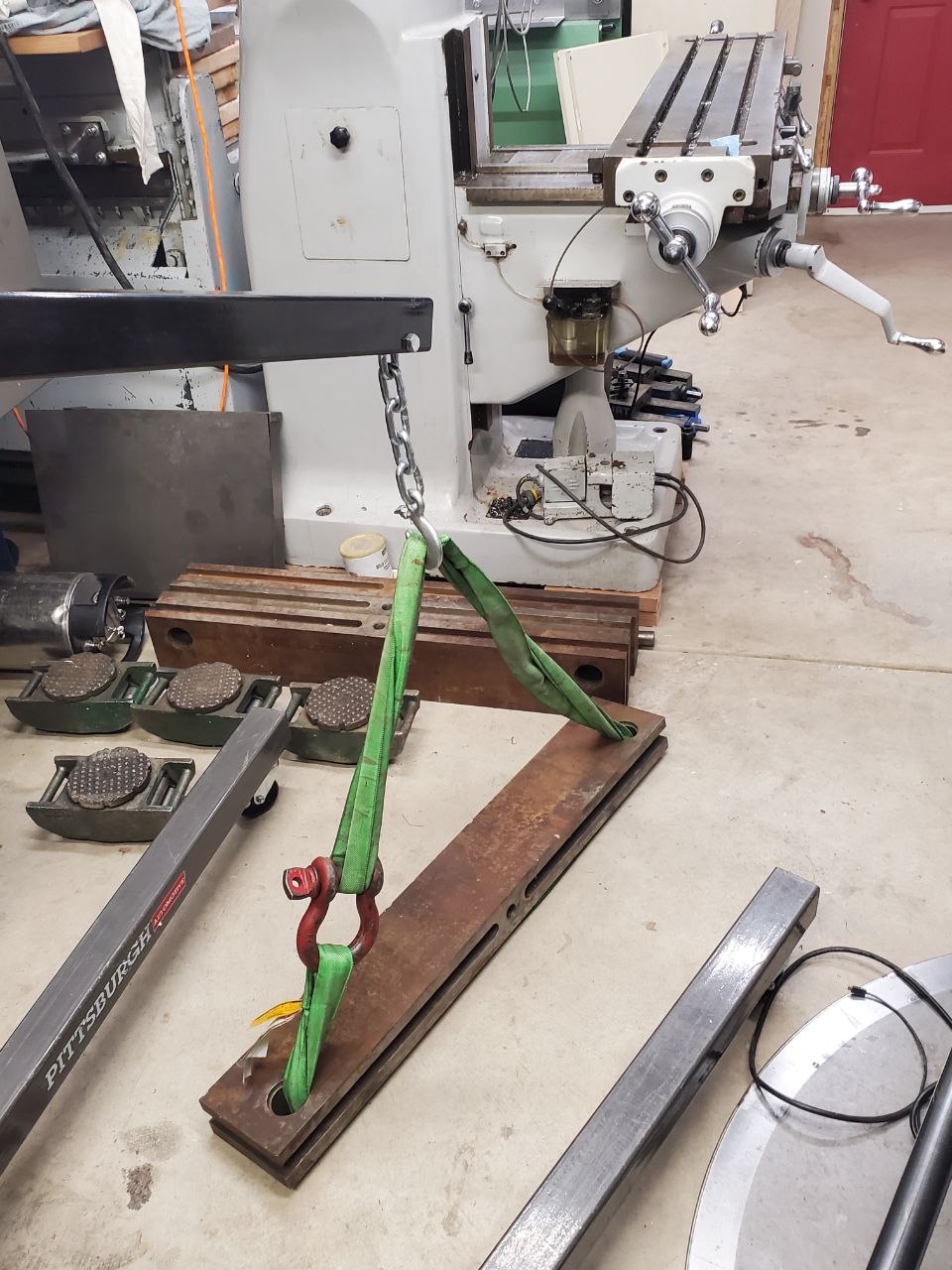 ...nothing that a couple 200 lb metal chucks cant fix.
 I machined a couple of dowels at the right spots to fit inside the tube leveling feet so I never have to think about it moving around on me.
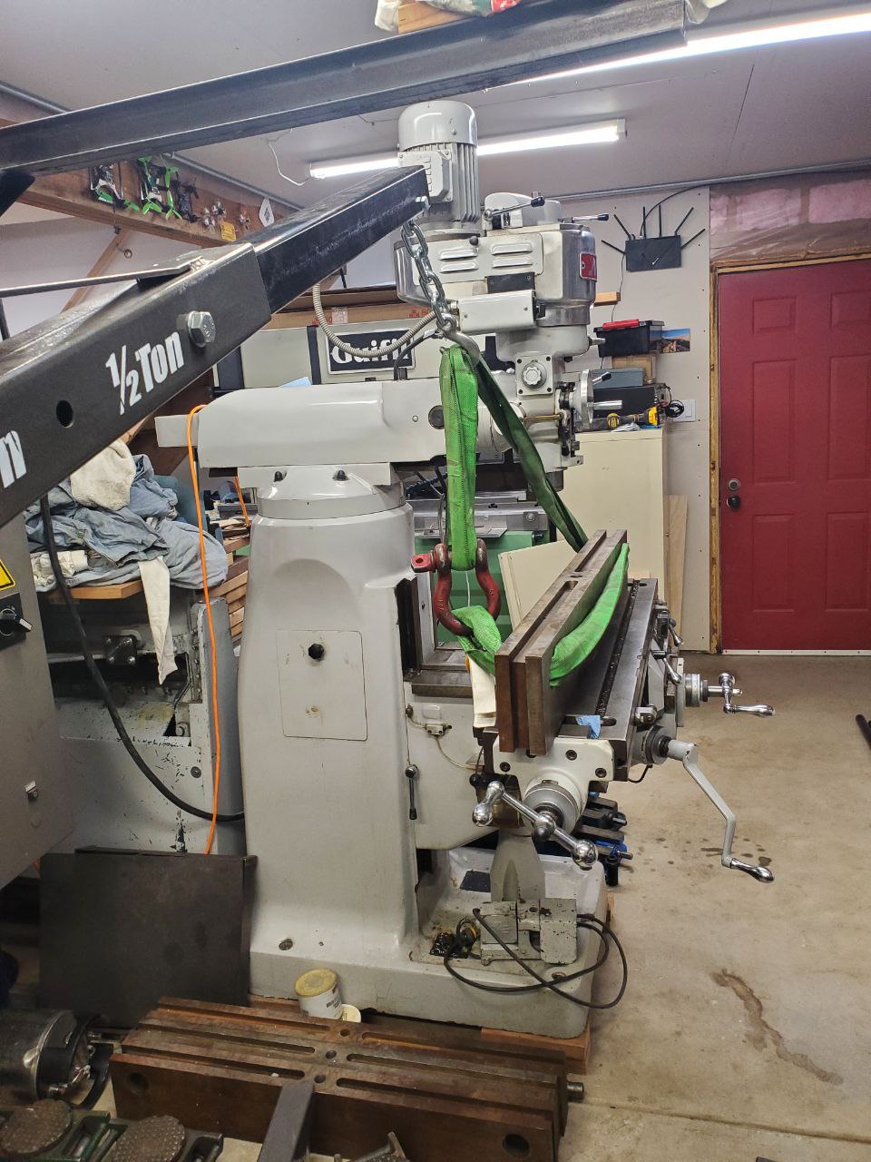
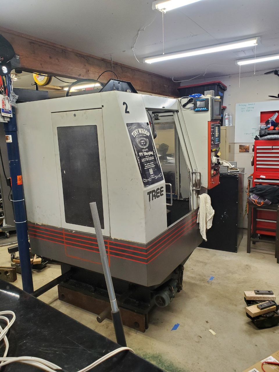
 Now my machine has a 6" lift! I knew the 4x4 days would come in handy.
 Much better!
Attachments:
The following user(s) said Thank You: tommylight, Unlogic
Please Log in or Create an account to join the conversation.
- chrisfischer
- Offline
- Senior Member
-
Less
More
- Posts: 44
- Thank you received: 10
20 Jun 2024 23:21 #303452
by chrisfischer
Replied by chrisfischer on topic Tree Kira VTC30 Retrofit
The next thing to do was get to know the bearings and screws. There was plenty of grime to clean.
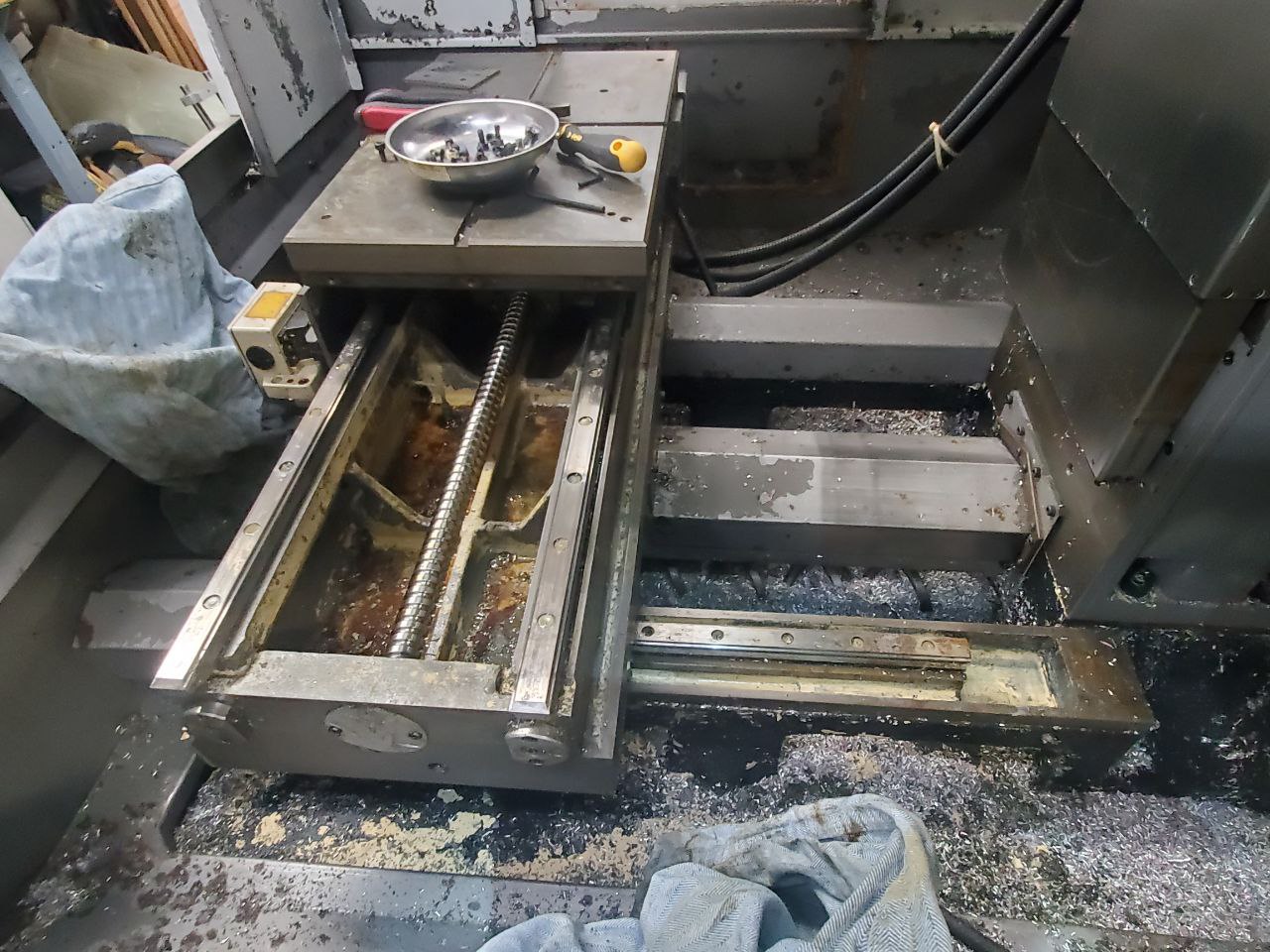
Turns out there is some slop and rust in the x thrust bearing so I got some of those in the mail for x and y.
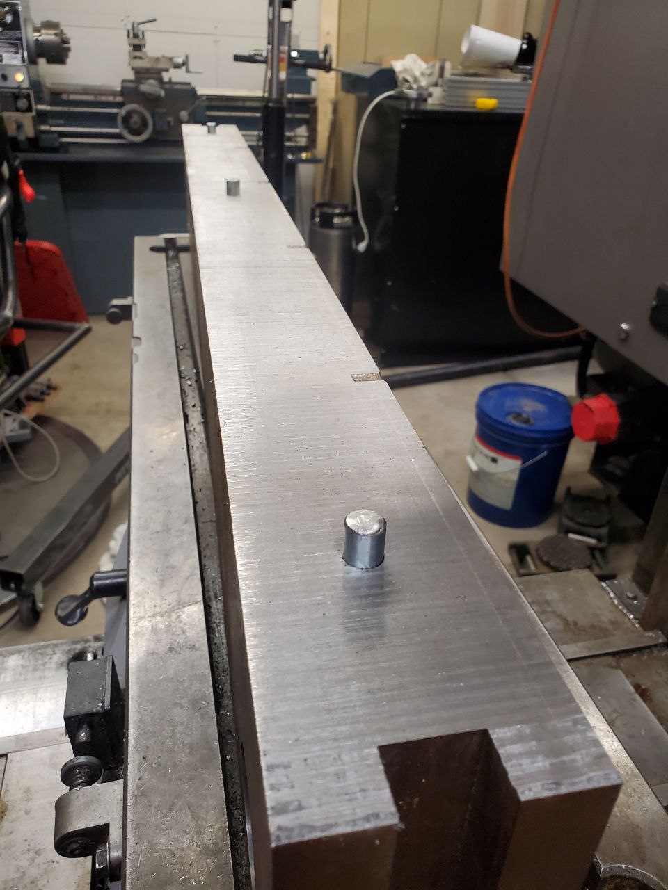
Next I needed to make a fixture plate for vises since the tslot table top was missing.
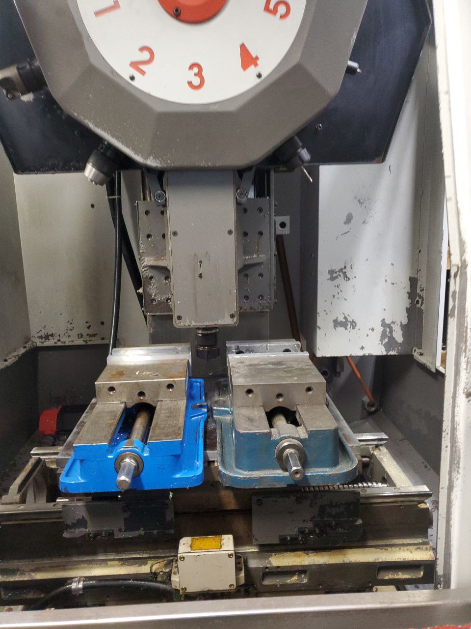
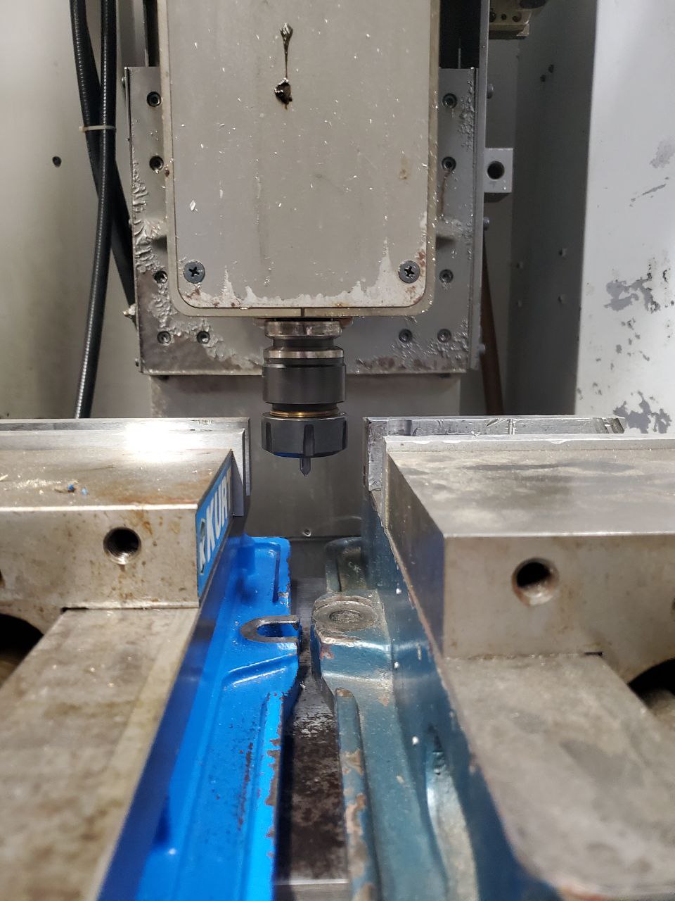
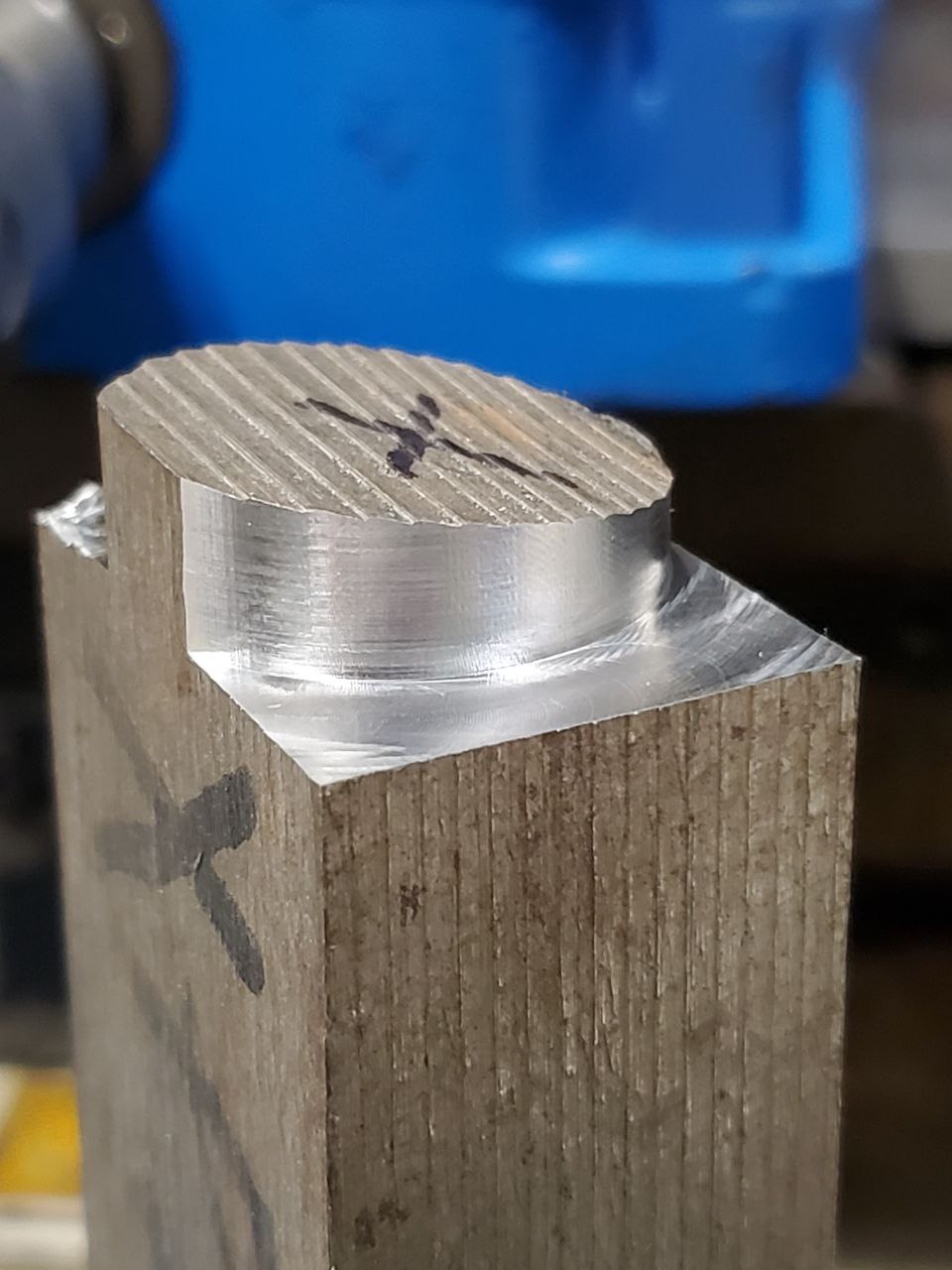
Then I did some test cuts in aluminum to see how the mechanicals are doing.

Then some cuts in tool steel. Some minor chatter with a ten thou stepover but Im pretty satisfied.
Turns out there is some slop and rust in the x thrust bearing so I got some of those in the mail for x and y.
Next I needed to make a fixture plate for vises since the tslot table top was missing.
Then I did some test cuts in aluminum to see how the mechanicals are doing.
Then some cuts in tool steel. Some minor chatter with a ten thou stepover but Im pretty satisfied.
Attachments:
Please Log in or Create an account to join the conversation.
- chrisfischer
- Offline
- Senior Member
-
Less
More
- Posts: 44
- Thank you received: 10
20 Jun 2024 23:33 - 20 Jun 2024 23:36 #303454
by chrisfischer
Replied by chrisfischer on topic Tree Kira VTC30 Retrofit
I didnt know it when I got it but the Fanuc O-Mate control does have rs232 but does NOT have drip feed. Which means it can only ever machine a program smaller than 32kb. Not interested. Also I looked into upgrading the fanuc or something and it wasnt long before I was also not interested. Thank god for Linux CNC because I can now upgrade the heck out of this thing rather than sink time and money into 1990s fanuc.
So the plan so far is to piggy back off Marco Reps Leadshine ethercat video and replace the motors and drives. I started to go down other cheaper routes but I decided to splurge on ethercat for future lights out and automation ideas.
EL8 Drives: www.leadshine.com/product-detail/EL8-EC750F.html
750w Motors: www.leadshine.com/product-detail/ELM1H-0750MA80F.html
I have been researching what vfd to use in order to truely get rid of all the fanuc (besides the spindle motor) and have just purchased a version 3 WJ200-037LF from ebay for $240. Crazy cheap.
Last edit: 20 Jun 2024 23:36 by chrisfischer.
Please Log in or Create an account to join the conversation.
- chrisfischer
- Offline
- Senior Member
-
Less
More
- Posts: 44
- Thank you received: 10
21 Jun 2024 17:26 #303502
by chrisfischer
Replied by chrisfischer on topic Tree Kira VTC30 Retrofit
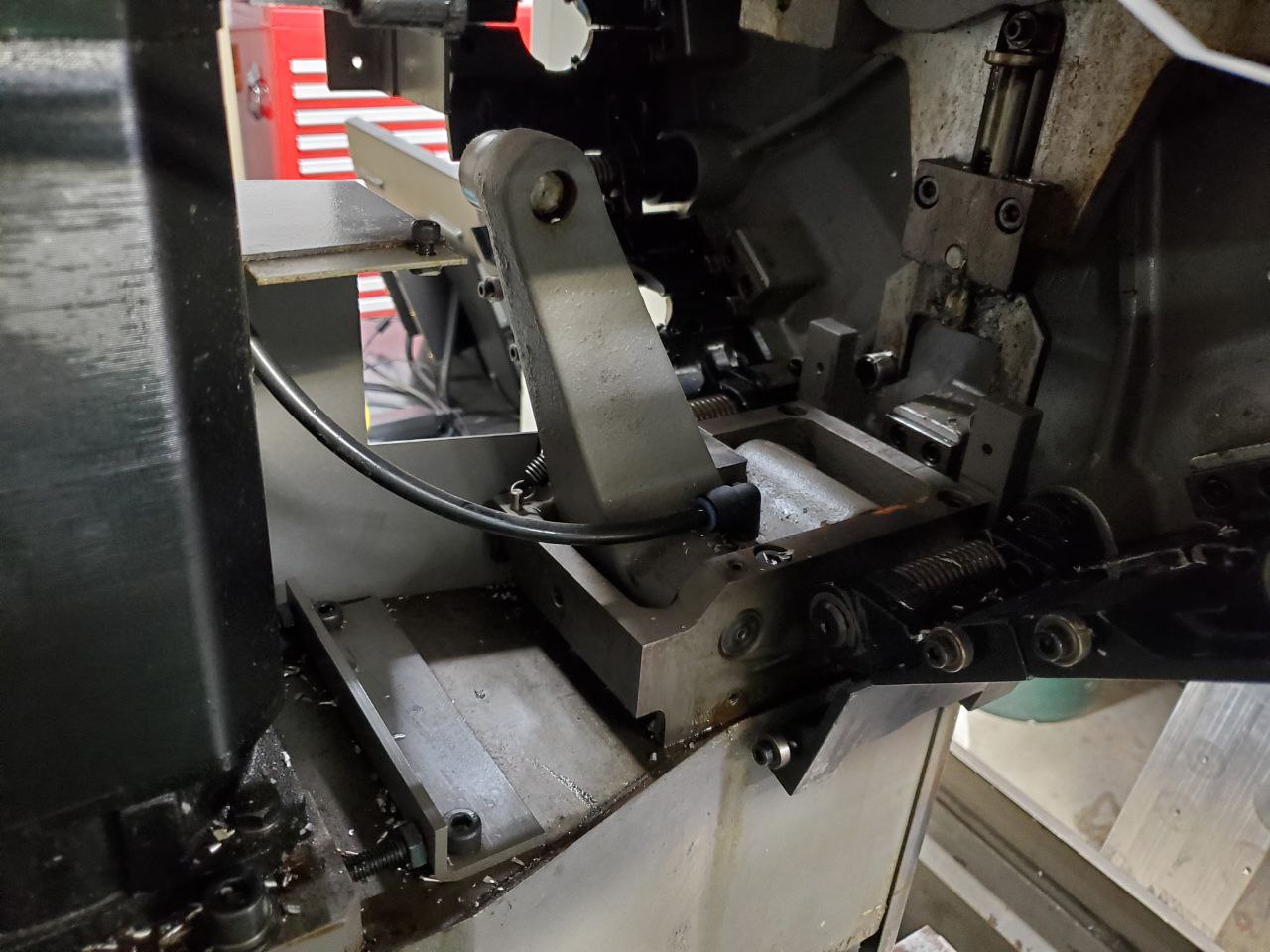
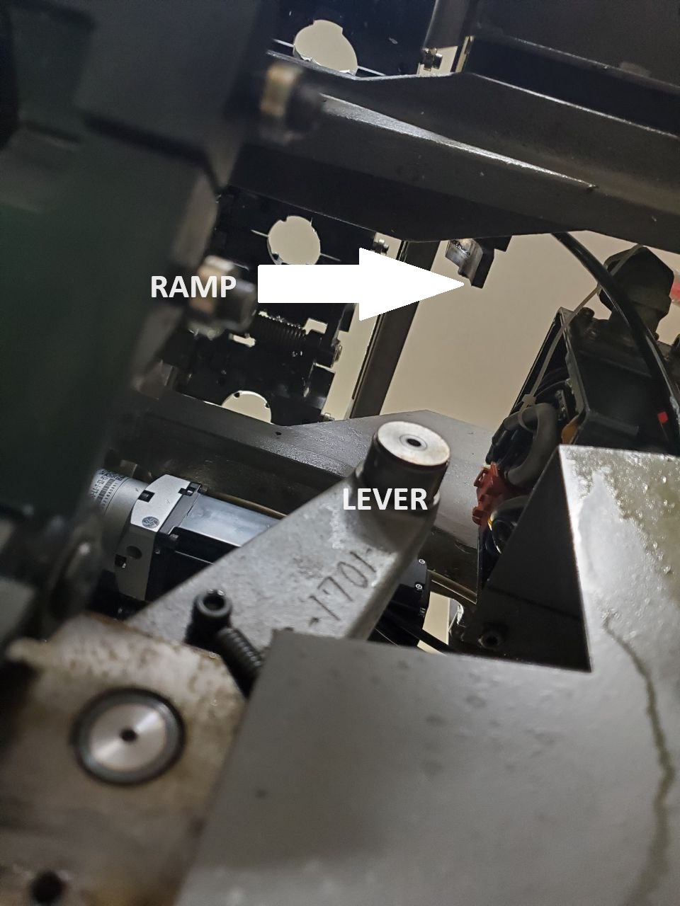
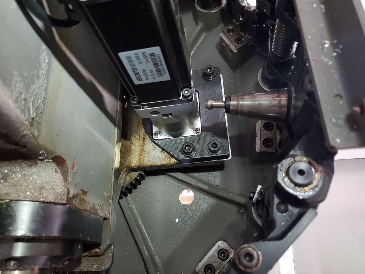
The tool changer on this thing is relatively simple. Which makes it more attractive for the retrofit. There is no pnuematic drawbar release. Instead it has a big lever arm that rides up a ramp. This mechanically releases the tool at the right location and is controlled purely with the z axis.
Attachments:
Please Log in or Create an account to join the conversation.
- chrisfischer
- Offline
- Senior Member
-
Less
More
- Posts: 44
- Thank you received: 10
21 Jun 2024 17:46 #303504
by chrisfischer
Replied by chrisfischer on topic Tree Kira VTC30 Retrofit
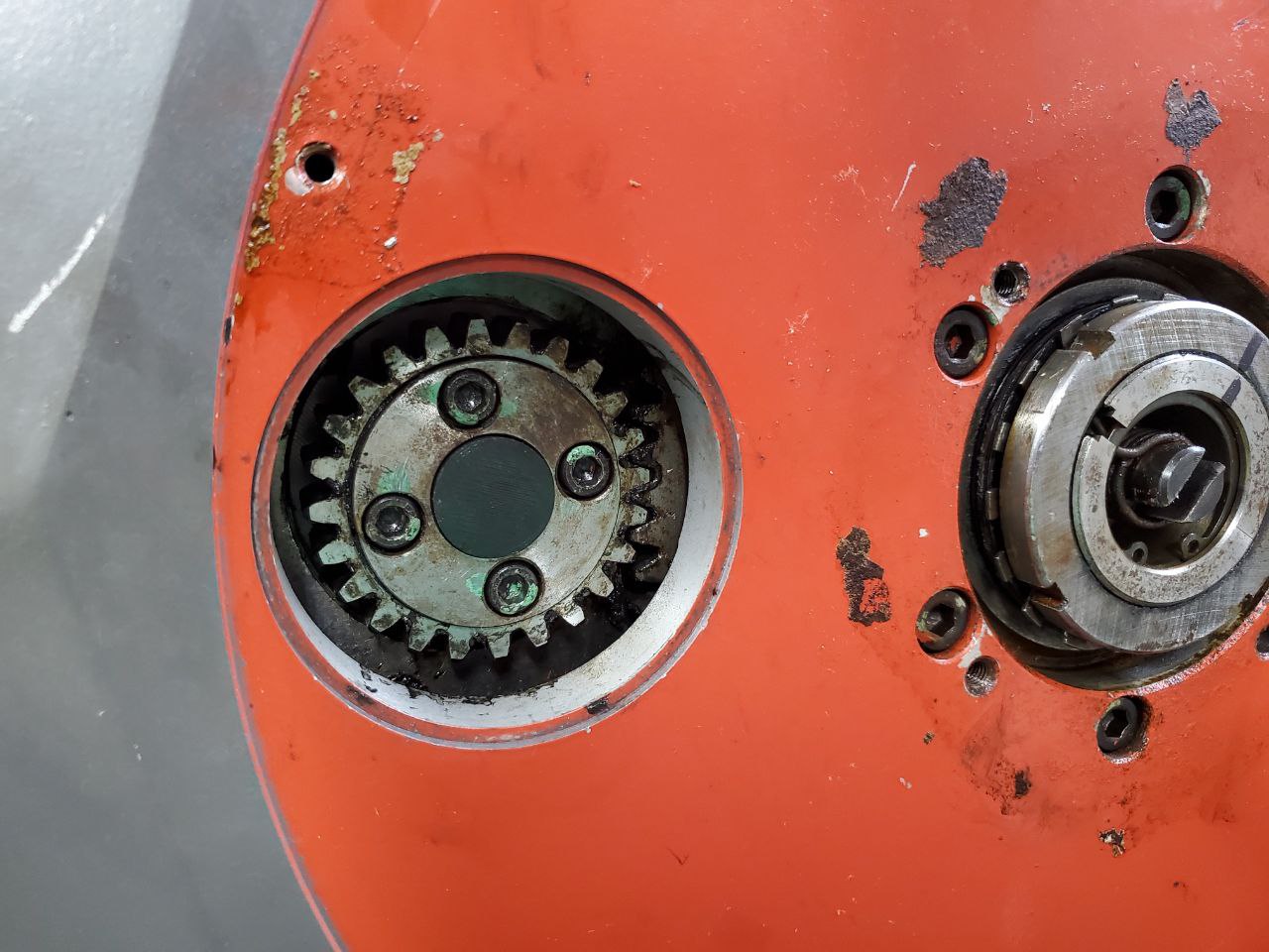
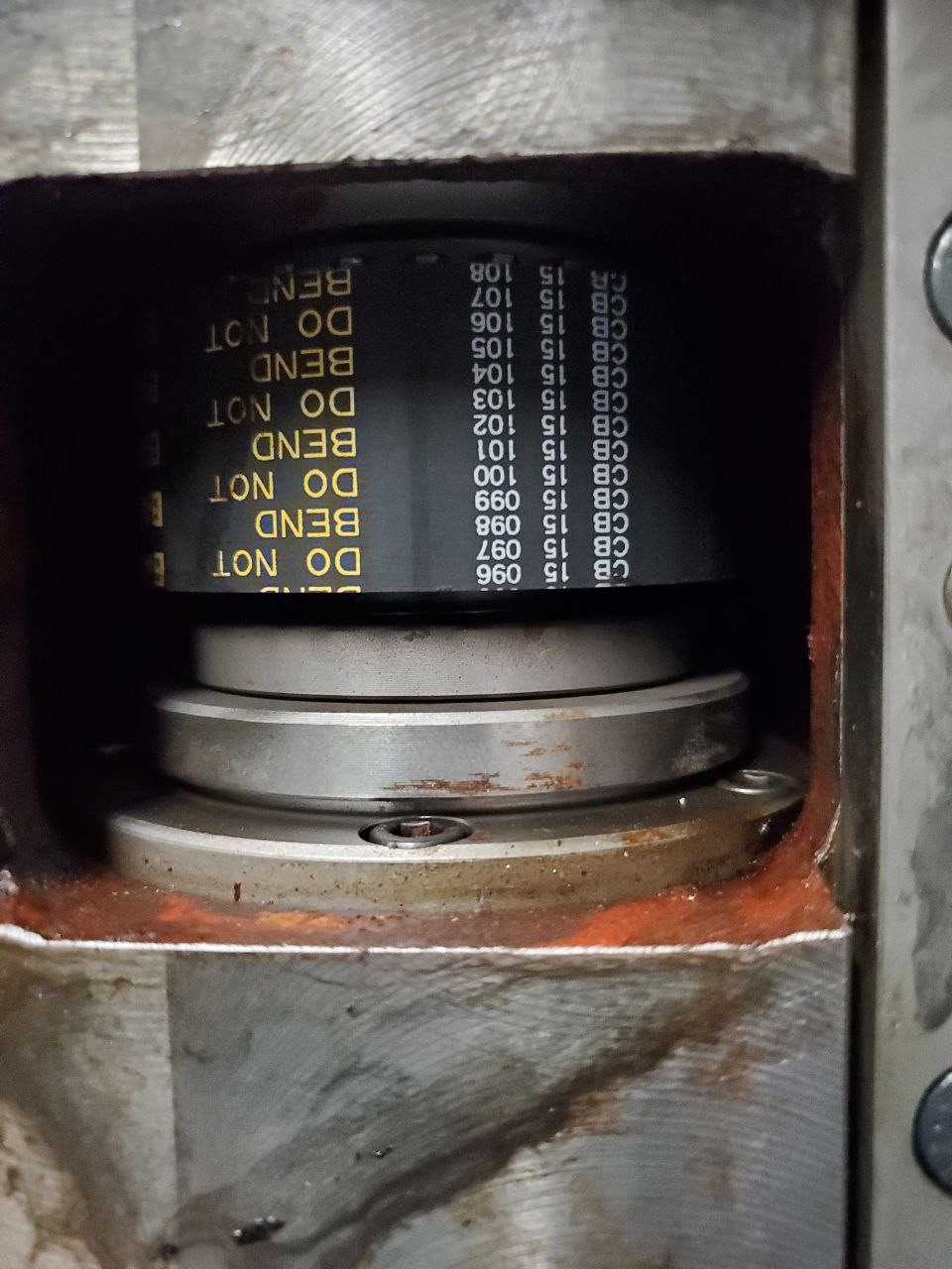
The tool carousel rotates around the spindle when the spindle is raised to a second home switch above the normal travel. This is just like more modern brother machines.
It uses a "dumb" induction motor to move the carousel to each pot location. There are hall switches on the motor shaft that read timing dogs. Those switches turn on or off the relay and brake - sending 3 phase wall power, then removing the power, then shorting the motor wires. This works in conjunction with a geneva gearbox.
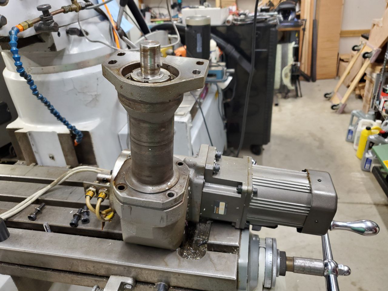
The gearbox output has a dead zone of about 30 degrees or so that doesnt rotate and isnt back driveable. This gives enough precision for the carousel to move to its pot location and stay put until controlled to move again. Its neat to see how back in 1990 what design decisions they went with. Spend the money on expensive gearboxes but cheaper motor/control. Unfortunately the carousel moves through its travel very cluncky starting and stopping with great energy spent at each tool pot. Much to my delight it was very easy to replace the geneva gearbox/induction motor with a 60mm servo and planetary gearbox. Now I can simply use g code to control an axis with smooth accelerations and drive to the pot I need rather than stop and start at each one at full current!
I drew up a bracket and 3d printed it to mount the servo.
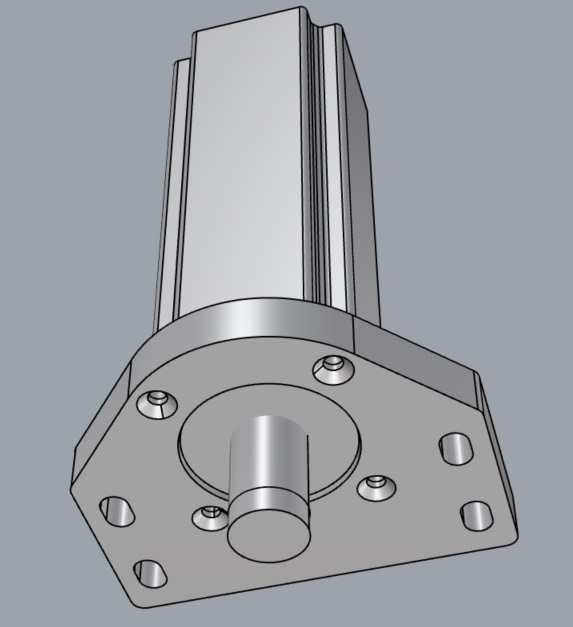
Then I drew up and printed a shaft size adapter to go from the 14mm my servo has to the 22mm the carousel needs.
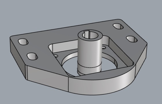
The prints are just pla but 100% infill and they will work great until the retrofit is done and I can machine brackets in metal.
Pretty damn satisfying solution.
You can see how the tools pull stud clears with room to spare!
It uses a "dumb" induction motor to move the carousel to each pot location. There are hall switches on the motor shaft that read timing dogs. Those switches turn on or off the relay and brake - sending 3 phase wall power, then removing the power, then shorting the motor wires. This works in conjunction with a geneva gearbox.
The gearbox output has a dead zone of about 30 degrees or so that doesnt rotate and isnt back driveable. This gives enough precision for the carousel to move to its pot location and stay put until controlled to move again. Its neat to see how back in 1990 what design decisions they went with. Spend the money on expensive gearboxes but cheaper motor/control. Unfortunately the carousel moves through its travel very cluncky starting and stopping with great energy spent at each tool pot. Much to my delight it was very easy to replace the geneva gearbox/induction motor with a 60mm servo and planetary gearbox. Now I can simply use g code to control an axis with smooth accelerations and drive to the pot I need rather than stop and start at each one at full current!
I drew up a bracket and 3d printed it to mount the servo.
Then I drew up and printed a shaft size adapter to go from the 14mm my servo has to the 22mm the carousel needs.
The prints are just pla but 100% infill and they will work great until the retrofit is done and I can machine brackets in metal.
Pretty damn satisfying solution.
You can see how the tools pull stud clears with room to spare!
Attachments:
Please Log in or Create an account to join the conversation.
- chrisfischer
- Offline
- Senior Member
-
Less
More
- Posts: 44
- Thank you received: 10
21 Jun 2024 17:54 #303505
by chrisfischer
Replied by chrisfischer on topic Tree Kira VTC30 Retrofit
I popped the cover off the spindle belt.
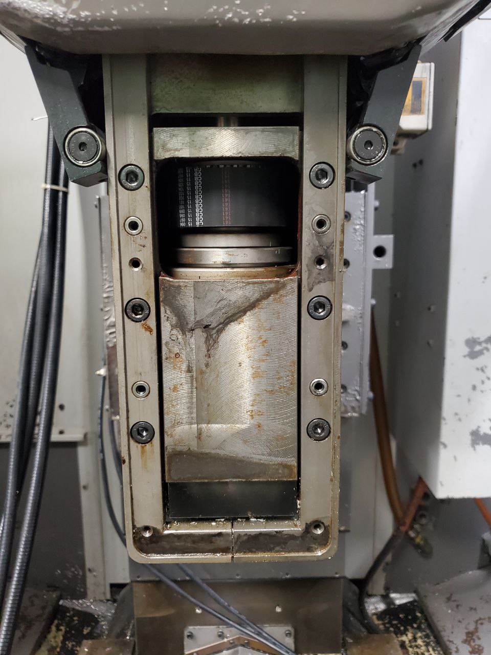
Looks like its in great condition (from what I can see).
Looks like its in great condition (from what I can see).
Attachments:
Please Log in or Create an account to join the conversation.
- chrisfischer
- Offline
- Senior Member
-
Less
More
- Posts: 44
- Thank you received: 10
21 Jun 2024 18:10 #303507
by chrisfischer
Replied by chrisfischer on topic Tree Kira VTC30 Retrofit
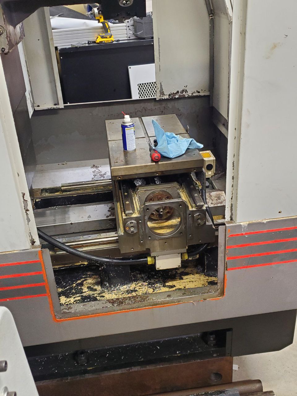
There are 3 limit switches for xy and z. From what I can tell there is a hard e stop switch (and this has dogs on both ends of the travel), there is a switch at the bottom that I'm pretty sure only tells the control to slow down and approach. Then there is the actual limit switch in the middle. The confusing thing is that when the middle switch is triggered the axis keeps moving until it gets to a few millimeters before the estop switch. So my assumption is the control see the middle switch then moves at the same rate to a soft limit and calls that machine zero. Why do you guys think they do that? Why not have the dog in the right spot to just stop?
This photo shows the x axis homed.
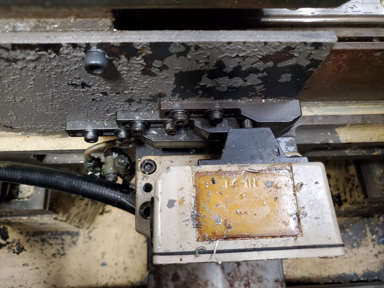
This photo shows the x axis homed.
Attachments:
The following user(s) said Thank You: tommylight
Please Log in or Create an account to join the conversation.
- tommylight
-

- Offline
- Moderator
-

Less
More
- Posts: 21747
- Thank you received: 7433
21 Jun 2024 19:04 #303510
by tommylight
Replied by tommylight on topic Tree Kira VTC30 Retrofit
If the original motors were DC servo, all machines must have what i call "extreme limits", and if those are tripped, the power to the drives gets cut completely.
That is to prevent runout in case the drive output transistors fail in short circuit as that would send the motors at full speed to one side, depending on what side of transistors failed.
If that is the case, i would leave that part of the wiring as is and just add E-stop to it.
That is to prevent runout in case the drive output transistors fail in short circuit as that would send the motors at full speed to one side, depending on what side of transistors failed.
If that is the case, i would leave that part of the wiring as is and just add E-stop to it.
Please Log in or Create an account to join the conversation.
- chrisfischer
- Offline
- Senior Member
-
Less
More
- Posts: 44
- Thank you received: 10
21 Jun 2024 22:09 #303517
by chrisfischer
Replied by chrisfischer on topic Tree Kira VTC30 Retrofit
I agree the top switch in this case is an estop switch and has a dog on both sides of the travel. Its already plumbed to the EMX relay for estop.
Please Log in or Create an account to join the conversation.
- chrisfischer
- Offline
- Senior Member
-
Less
More
- Posts: 44
- Thank you received: 10
21 Jun 2024 22:19 #303518
by chrisfischer
Replied by chrisfischer on topic Tree Kira VTC30 Retrofit
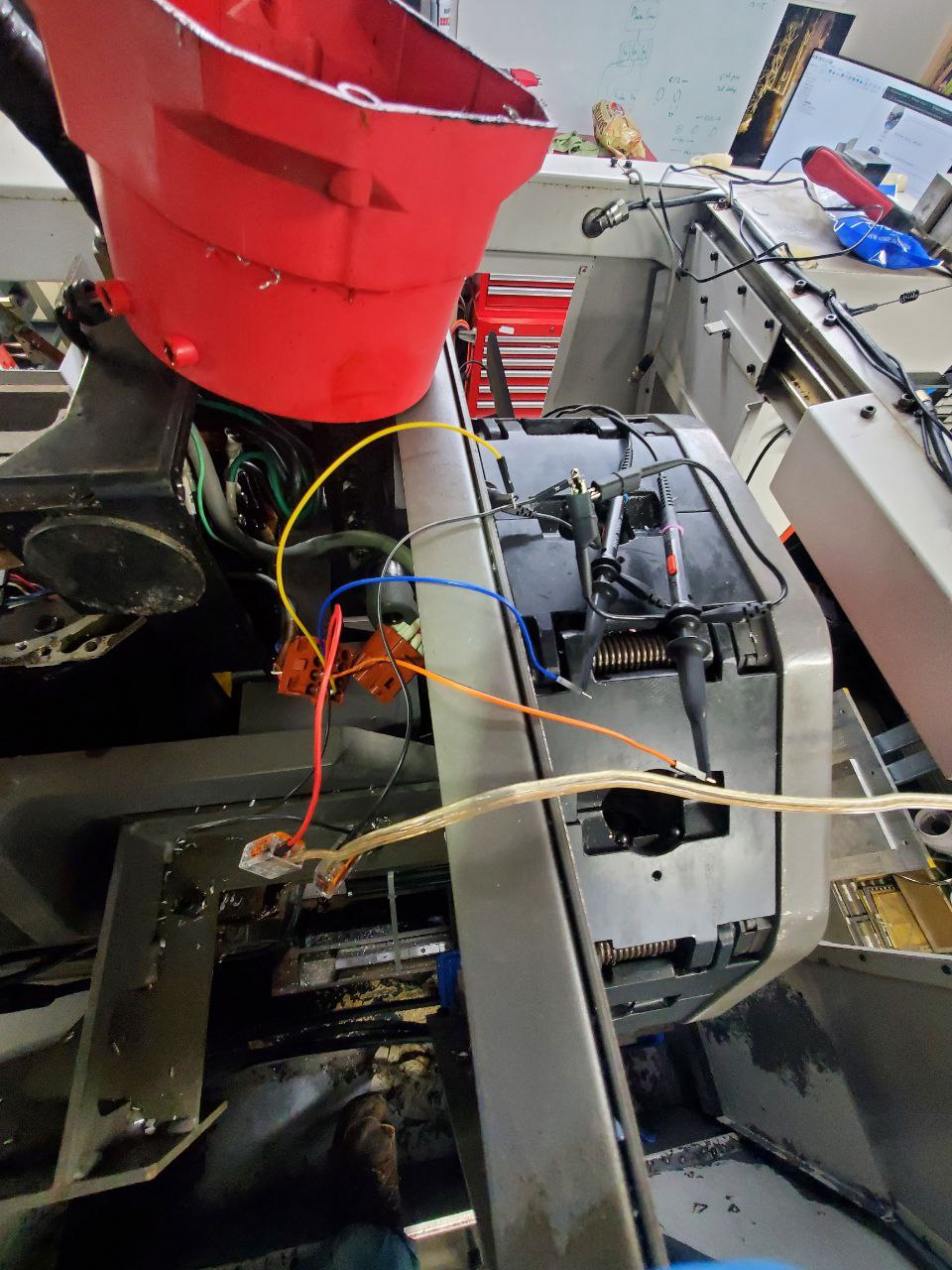
I was messing around in the back of the orange plug for the spindle encoder trying to understand the pinout, or at least the power wires. The multimeter readings were fussy and I made my first mistake of the build allowing a wire to short. Now the machine powers up in estop with an overload light. Not sure I can or will fix that.
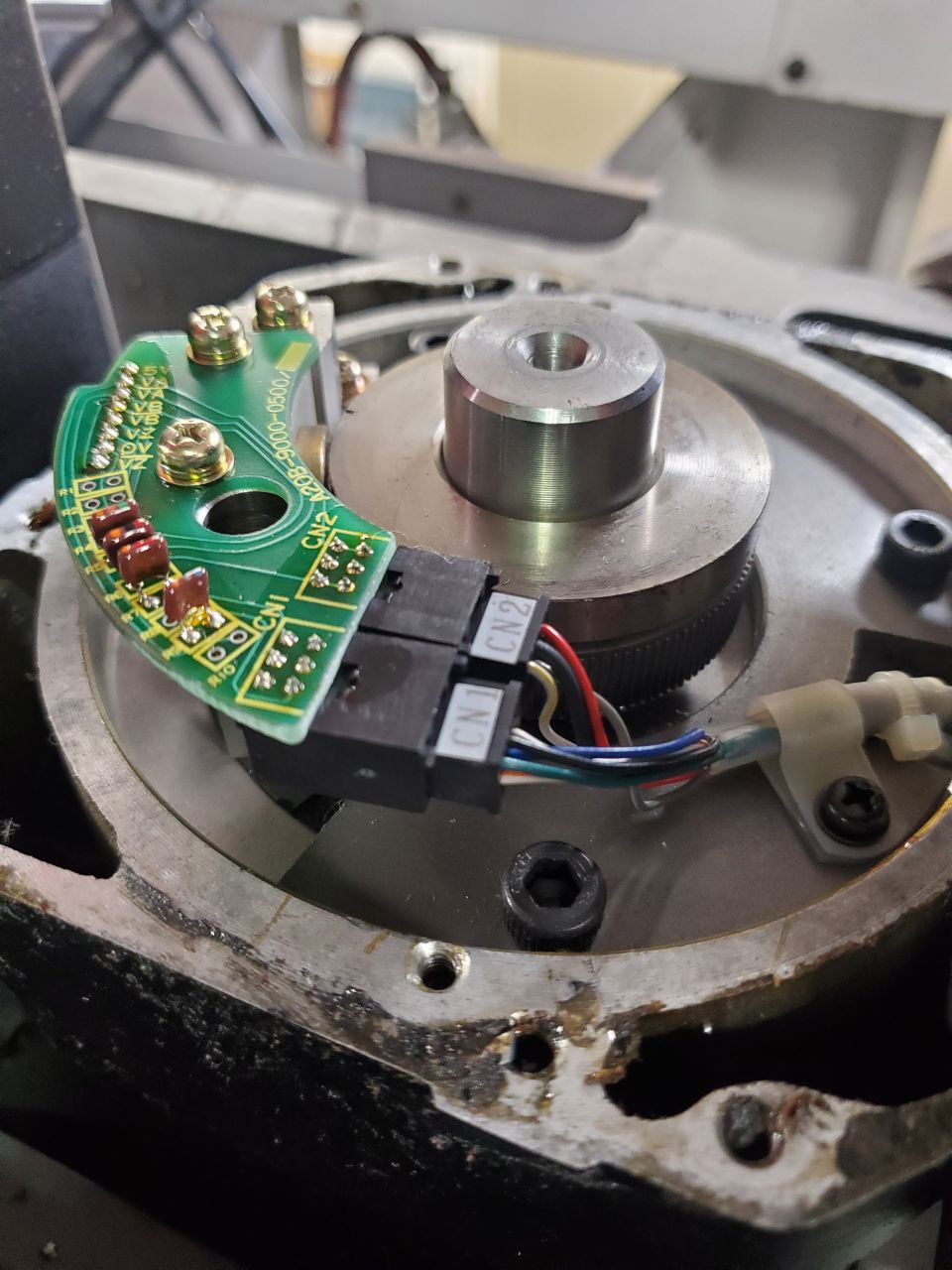
So instead I took the spindle cooling fan off to expose the encoder and lucky me the pinout is called on the pcb!
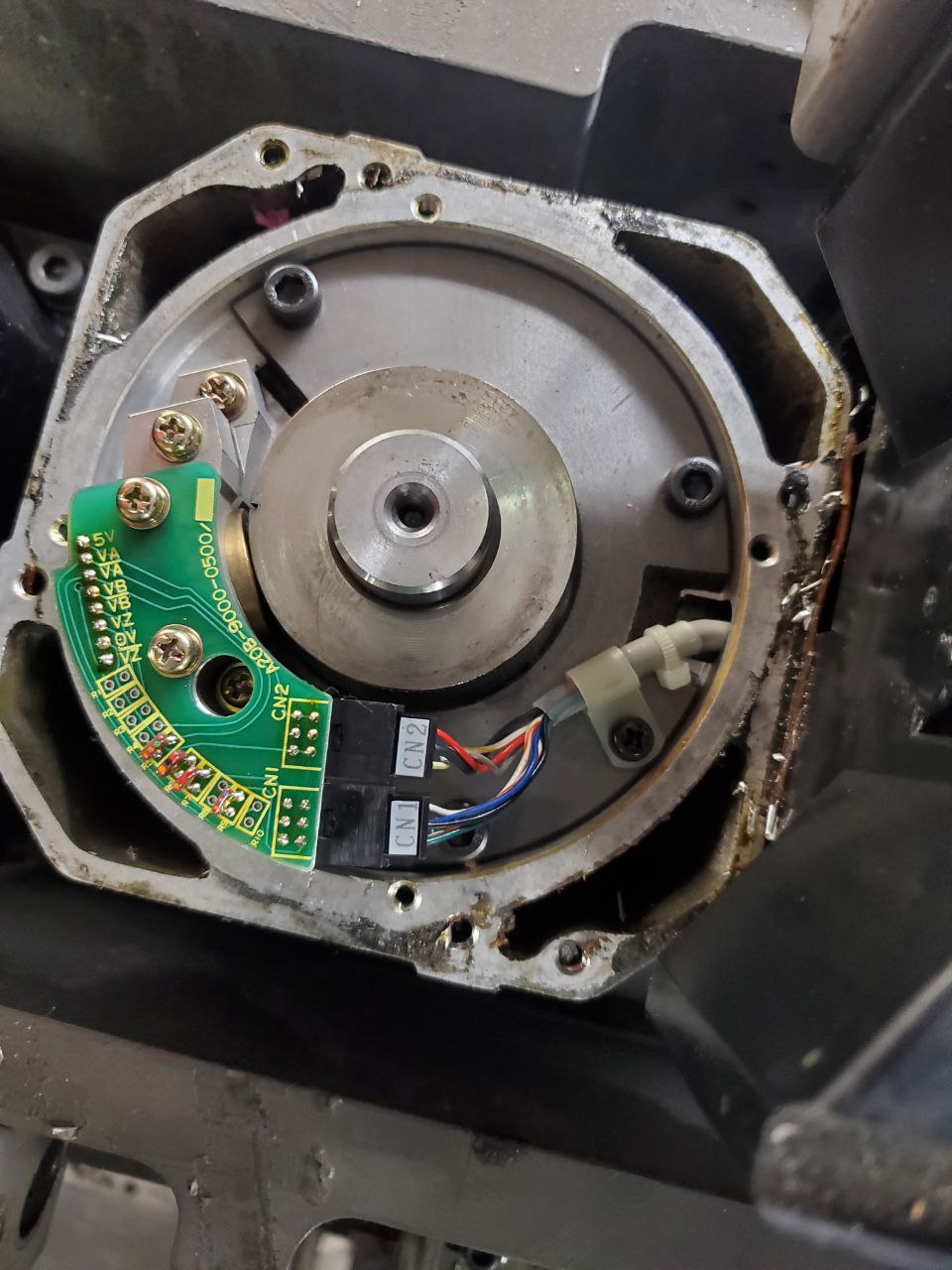
So I soldered up some header pins to bullet connectors from back in the drone racing days. I wanted a much more stable wiring situation after that mistake.
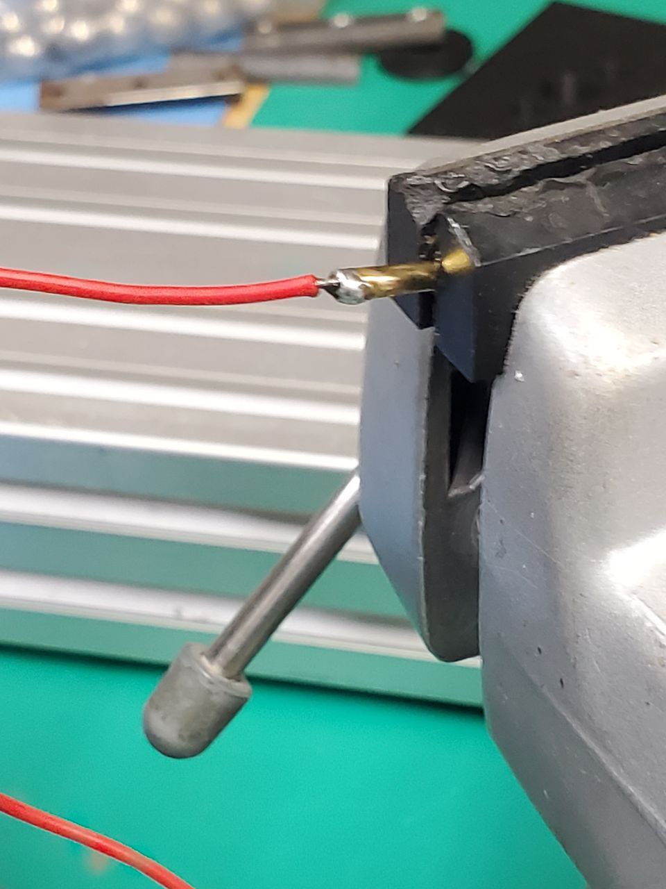
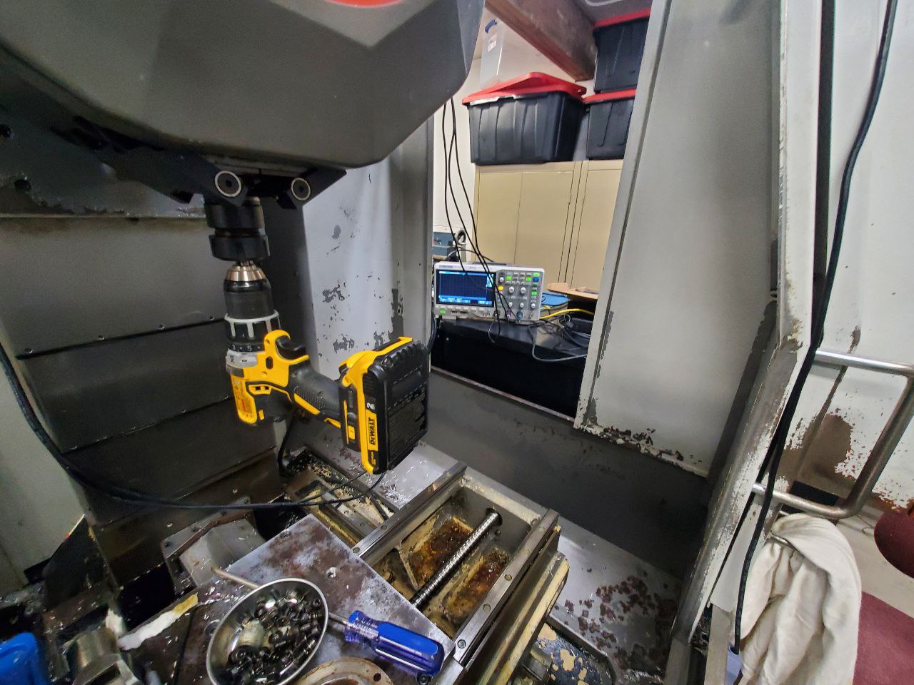
I carefully arranged connections to the scope.

Then I gave the spindle a turn.
Im happy to see the encoder doesnt seem damaged!
Im not sure why channel 2 (B+) is so low on voltage. I had to scale the axis a lot more than the others.
You can see the timing and sinusoidal output of this encoder.
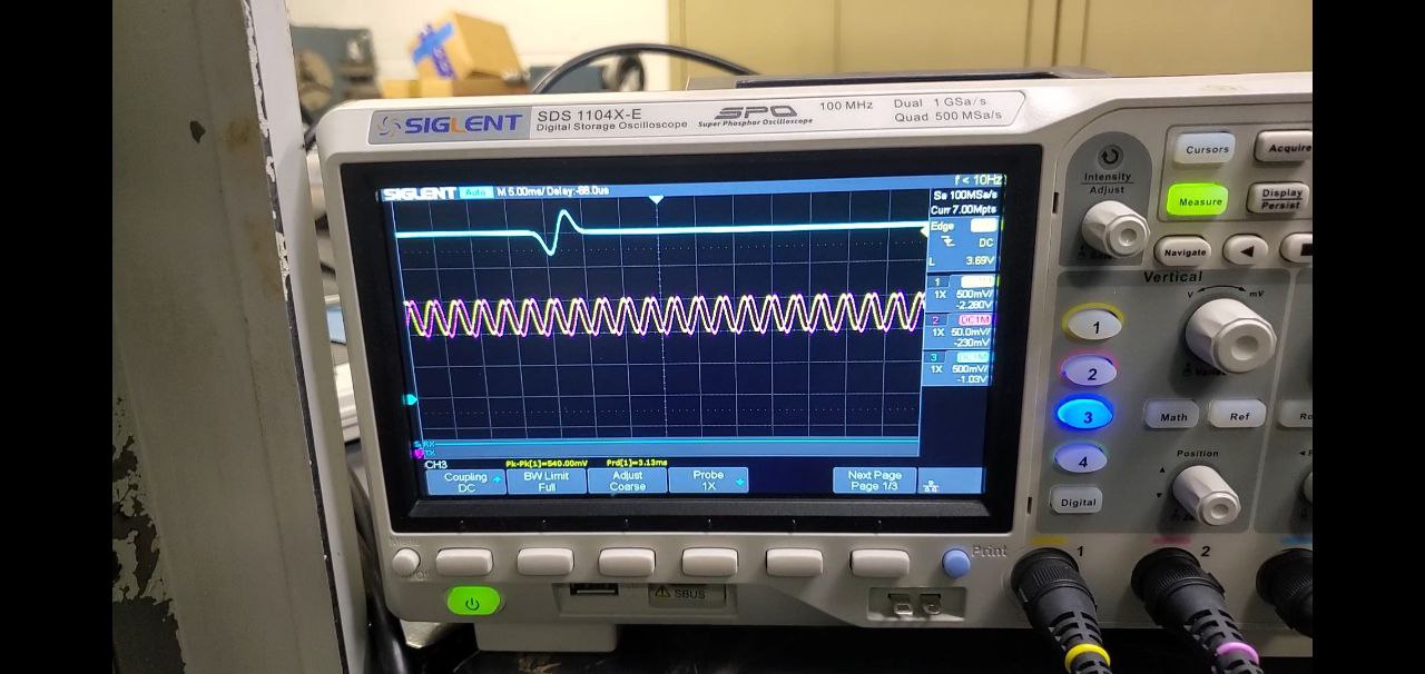
Any clever suggestions on how to get the resolution without having to count the little bumps on that wheel? Maybe I could rig a tach signal up on the spindle in the scope and compare. That would tell me the belt ratio too which I have no idea what it is.
So instead I took the spindle cooling fan off to expose the encoder and lucky me the pinout is called on the pcb!
So I soldered up some header pins to bullet connectors from back in the drone racing days. I wanted a much more stable wiring situation after that mistake.
I carefully arranged connections to the scope.
Then I gave the spindle a turn.
Im happy to see the encoder doesnt seem damaged!
Im not sure why channel 2 (B+) is so low on voltage. I had to scale the axis a lot more than the others.
You can see the timing and sinusoidal output of this encoder.
Any clever suggestions on how to get the resolution without having to count the little bumps on that wheel? Maybe I could rig a tach signal up on the spindle in the scope and compare. That would tell me the belt ratio too which I have no idea what it is.
Attachments:
Please Log in or Create an account to join the conversation.
Moderators: piasdom
Time to create page: 0.828 seconds