Tree Kira VTC30 Retrofit
- chrisfischer
- Offline
- Senior Member
-

Less
More
- Posts: 44
- Thank you received: 10
21 Jun 2024 22:24 #303519
by chrisfischer
Replied by chrisfischer on topic Tree Kira VTC30 Retrofit
Hmm looking at the photos I posted on the forum just now and the encoder has 0500 at the end of the part number. Maybe thats the resolution. Quick google search lists only old parts at high prices!
Please Log in or Create an account to join the conversation.
- tommylight
-

- Away
- Moderator
-

Less
More
- Posts: 21276
- Thank you received: 7265
21 Jun 2024 22:33 #303520
by tommylight
Replied by tommylight on topic Tree Kira VTC30 Retrofit
Here i go again bursting bubbles ... 
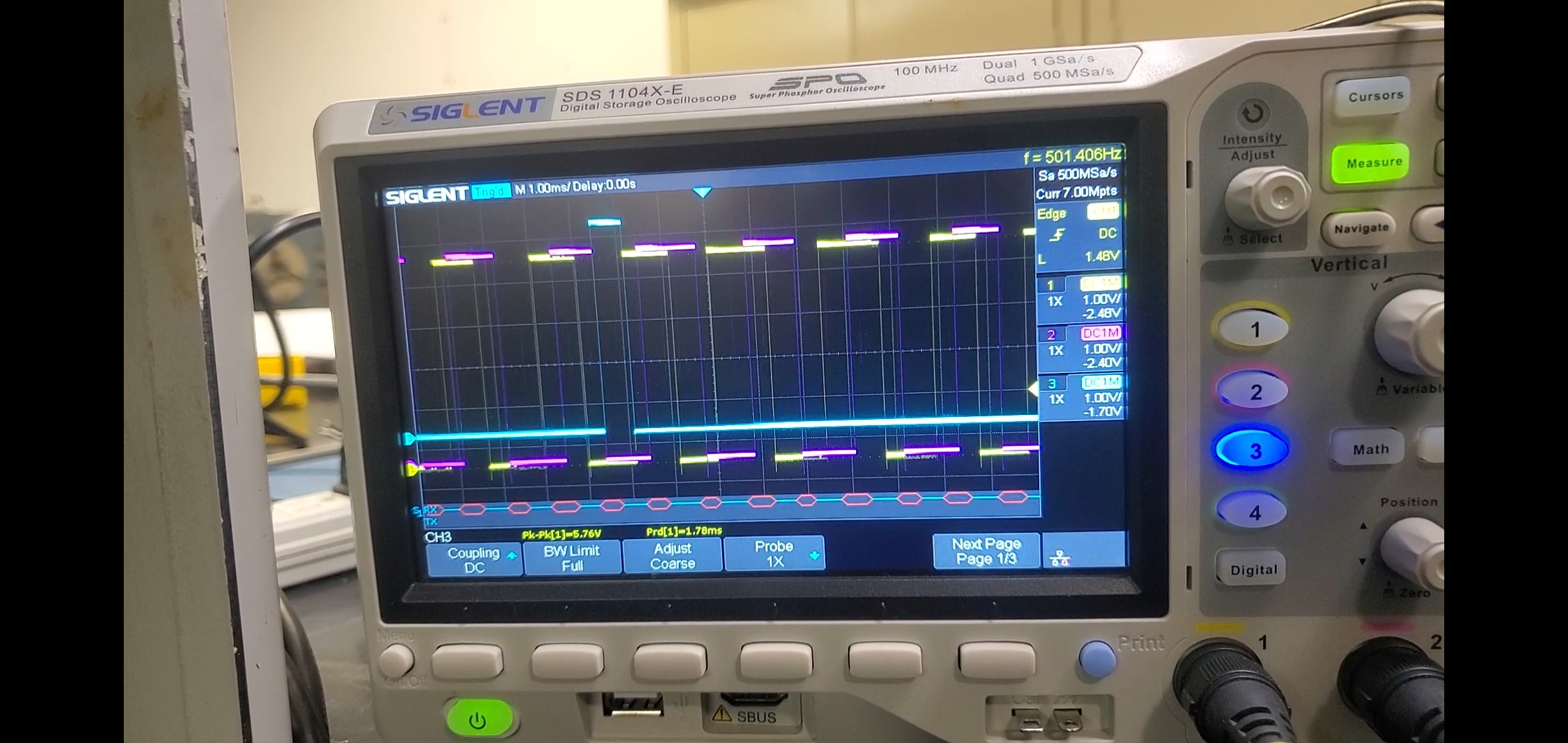
If it is an incremental encoder, and by the pictures it sure looks like it is, then the outputs should be square wave, and at least 3.5V peak to peak with no load, usually 4.2-4.5V.
Looking at the scope, having 540mV or 0.54V is no good, having a triangle to near sine wave signal is even less good.
Question, are you sure the scope probe is set at 1X, not 10X ?
Please Log in or Create an account to join the conversation.
- chrisfischer
- Offline
- Senior Member
-

Less
More
- Posts: 44
- Thank you received: 10
30 Jun 2024 00:02 #304069
by chrisfischer
Replied by chrisfischer on topic Tree Kira VTC30 Retrofit
I agree the waveform is weak.
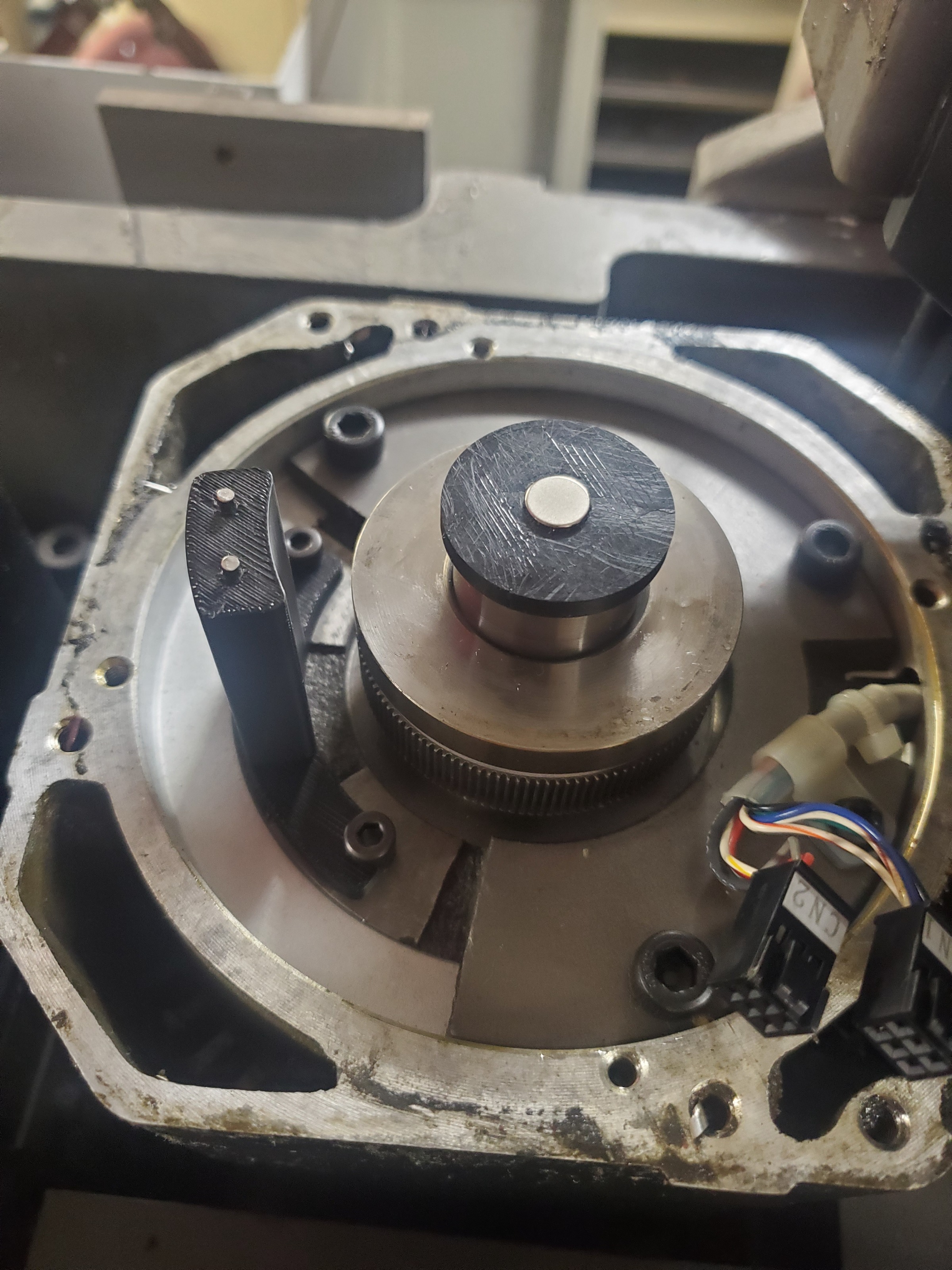
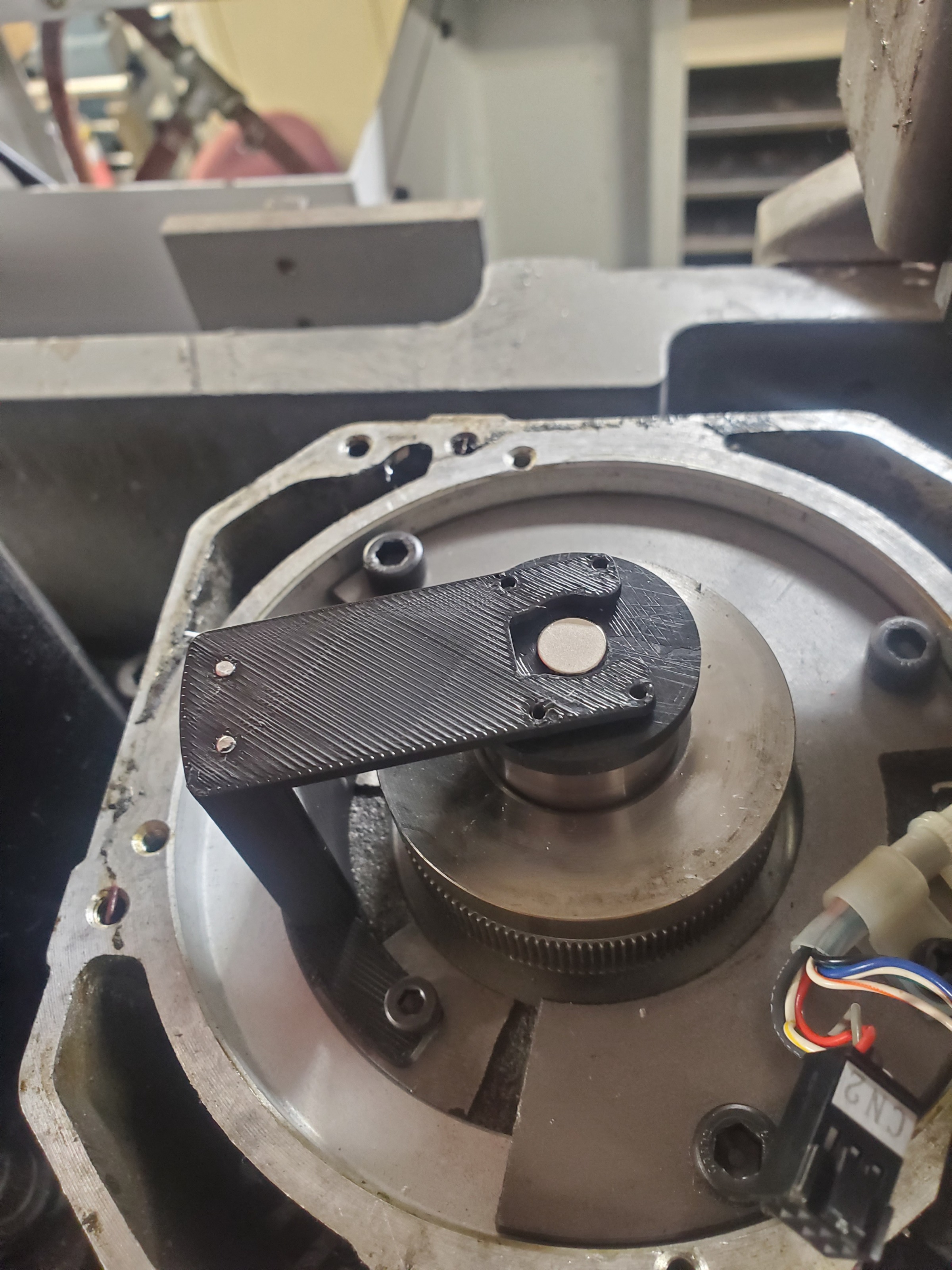
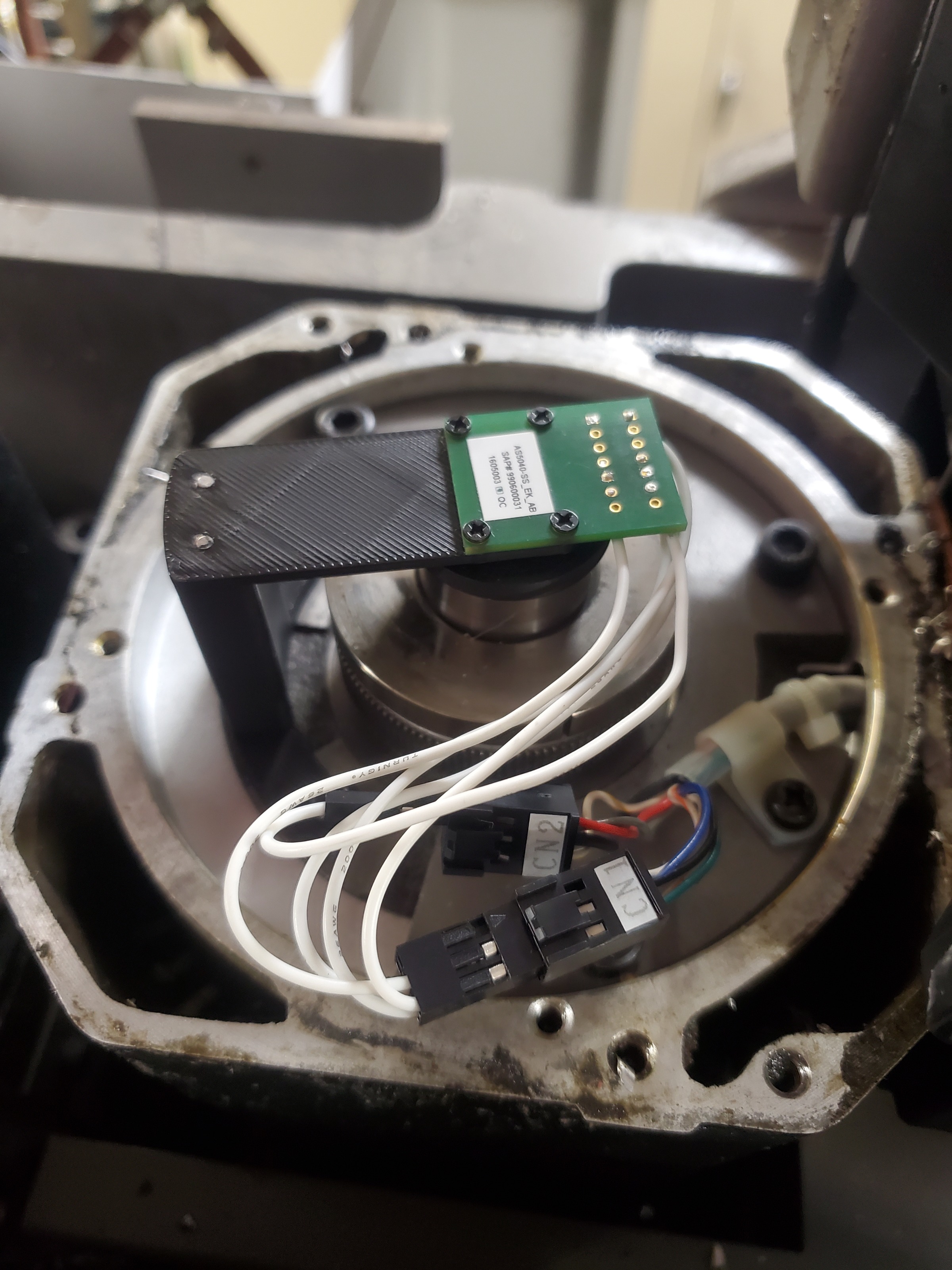
After some deliberation I decided to replace the encoder and try one of these cheap hall effect chips (AS5040). I chose this one because its 10 bit resolution matches the max I read in the WJ200 manual.
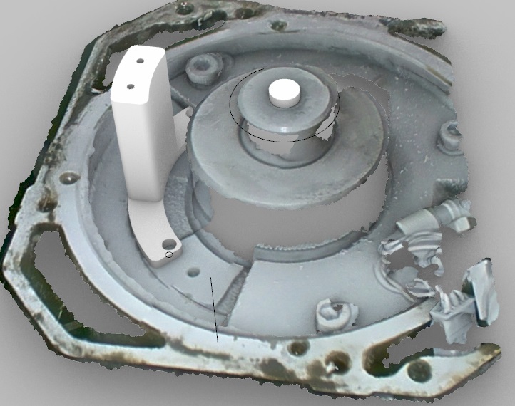
I 3d scanned the top of the servo drive to get the locations for things. (loving this Einstar scanner)
The scan wasnt perfect so I iterated the top diving board twice to dial it in.
Then I soldered up some wires and fed them to the fanuc wiring already in place.
Now I have a good 5v square waveform on A B and Z.
I will likely replace the 3d printed parts with metal parts once the machine is up and running. I wouldn't want to have problems because the servo gets warm down the road.
Attachments:
The following user(s) said Thank You: Unlogic
Please Log in or Create an account to join the conversation.
- chrisfischer
- Offline
- Senior Member
-

Less
More
- Posts: 44
- Thank you received: 10
02 Jul 2024 04:14 #304199
by chrisfischer
Replied by chrisfischer on topic Tree Kira VTC30 Retrofit
Trying to setup the Hitachi WJ200 with this fanuc spindle motor. I got the startup test to spin the motor in the Hitachi manual. As I look into interfacing the modbus with my 7i96, damn I'm in deeper than I can swim. I bought a few of the cheap usb to rs485 sticks as a stepping stone since there are more threads and youtube videos talking about that. Reading about the simple positioning (for tool change orientation) in the manual is not too simple either. I see the wiring for the encoder neglects the index and says channel a can be 5-24v but channel b can only be 24v.
Discouraging.
Discouraging.
Please Log in or Create an account to join the conversation.
Moderators: piasdom
Time to create page: 0.225 seconds

