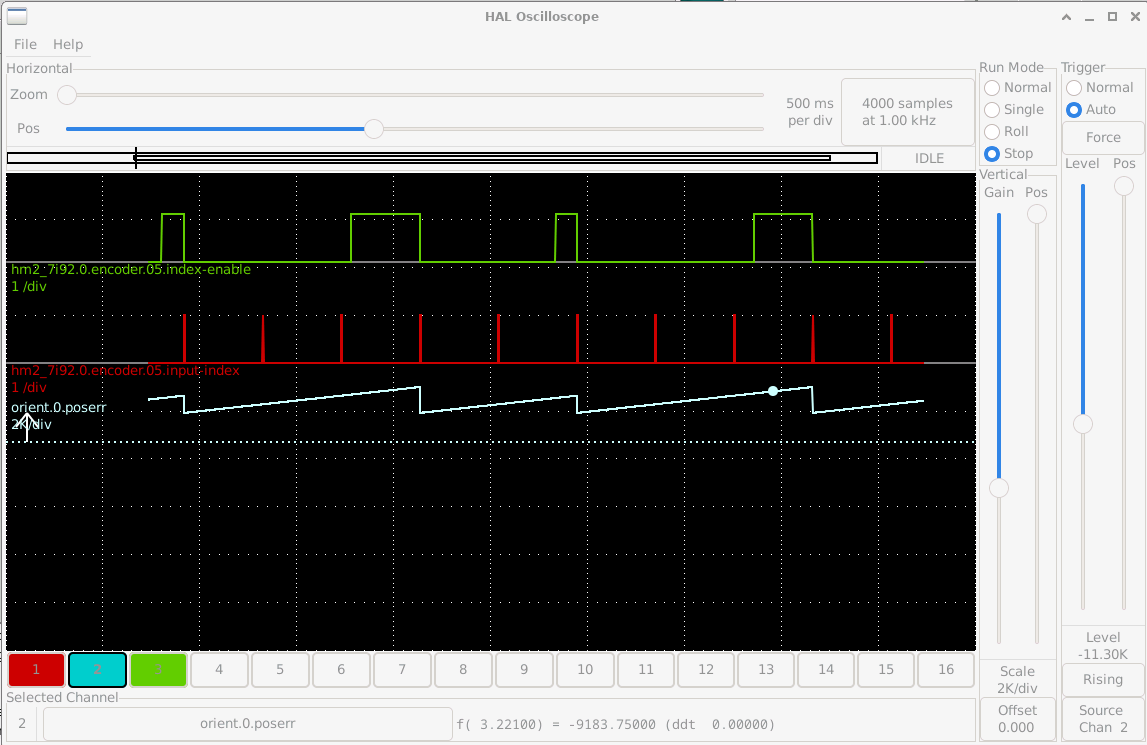
Its been some months since I started this quest, and only a week or so ago, I managed to get a reliable spindle orientation system working.
This was only achieved by working with that bright but sometimes impossibly childlike system, Co-Pilot.
Just about the same time I started looking at this, the 1983 parajust spindle vfd became unmendable, so I adopted a Yakagawa vfd and although it ran to me normally, I hadn't appreciated a few finer points, like what is the minimum rpm figure and what happens if the input stage receives a negative voltage indicating reverse, when the machine is setup to have a reversing relay.
So the basic premis is that the spindle, which is to all intentes direct driven as the motor is connected by a 1:1 HPD belt, has on it a 48 tooth wheel passing two hall effects sensors suitably spaced to output a quadrature signal. There is a separate single tooth index on the other edge of the pulley. The version of Linuxcnc is 2.9.3 and on a Raspberry PI (5) platform. The latter fact caused a lot of confusion as there are some subtle timing issues wrt to index pulses. Once overcome, the trying to use the Orient command failed as the orient window ends up being 22° wide, and maybe because the motion controller expects an encoder with over a thousand counts per rev, not 192. Anyway, means I cannot use Orient.
Neither could I use M19, and I could not find any pin that would light up when M19 called, so have adopted M119 as a custom command. (There is also an M109 to cancel M119, but not used as the M119 contains the shut down itself down after a wait.) M19 cannot be remapped as its too deep in the motion control, I believe.
The vfd can be set to run right down to less than 20rpm and the machine's spindle brake is hard wired into the vfd enable signal, so the only viable method I have found is to set the index enable, run the spindle until the index enable pin goes low, and disable the vfd and apply the brake.
You'll see from the attached hal file that this simple statement led to a complex solution.
The Normal spindle commands M3 and M4 on this machine do not require a spindle PID. The vfd on its own without any feedback runs the spindle stably and consistently, so is not implemented. Because I have a reversing relay, the vfd speed signal needs to be abs, so not to go negative. Also before I set out on this orientation quest, rigid tapping via M33.1 worked, so that encoder feedback requires being maintained.
This may not be elegant, but it does work for me, where none of the other methods, and I try try too many of them, didn't suit my hardware.
The actual code here was written by Co-Pilot and my relationship with 'him' has been interesting Just because he gets the syntax right once, don't be surprised when some iterations later, 'he' 'forgets' and has to be reminded. At times it has been extraordinarily frustating, but the way I see it is that he has read the whole forum, github releases and a lot more, so can guess at solutions, but won't know if something that was put forward actually worked, so if you engage in this kind of torture, you have to go back with facts, and he will rewrite, over and over..
One thing left over to solve is that when running at 3000 rpm say, and calling for a tool change, the spindle enable signal disappears and the spindle brake applies instantly, and to my mind its uneccessarily violent. I asked Co-Pilot to write me a soft stop that instead of simply cutting the enable signal, reduces the speed to 450 rpm speed, so the spindle is braked internally via the vfd and braking resisitor to a much slower speed before applying the brake. This is written, but not yet tested.