Unexpected waveform results
- CinciJeff
- Offline
- New Member
-

- Posts: 5
- Thank you received: 0
About 12 yrs ago I converted a Harbor Freight mill-drill to a ballscrew-driven 3-axis CNC. I built stepper drivers with kits from Camtronics (Dan Mauch), built my own 30V power supply, and used surplus Sanyo-Denki 103-845-6741 (big!) steppers for the X and Y axis. I ran the system with an ancient laptop running CNC Pro from Yeager Automation. I think the software is now unsupported freeware, but at the time it did (and still does) a decent job at driving my steppers. My machine has seen limited use, but every once in a while I'd fire it up to do some non-CNC work.
For the last few years I've wanted to upgrade the computer and software to increase the usability and performance of my machine. I bought a Dell Optiplex GX280 about 4 years ago with the intent of running EMC2. I tried and failed, and let it languish for another year or so. I now have a few projects I'd like to do on the mill, and this time I'm determined to get things up and running.
Currently I have LinuxCNC 2.5.2 (and the version of Ubuntu that came with it on the CD image) installed on the Dell GX280. I added a graphics card to try to minimize the latency, but I don't think it helped. My max level is about 44000.
Without knowing the exact specs of my stepper drivers, I set up a profile using the StepConf Wizard using conservative values of 10,000 for Step Time and Step Space. This resulted in no motion at all from my steppers. I tried tons of other combinations, and still nothing. I decided to take it to a lower level, so I hauled out my oscilloscope and looked at the waveforms from both LinuxCNC (not working) as well as CNCPro (working). Here's what I found:
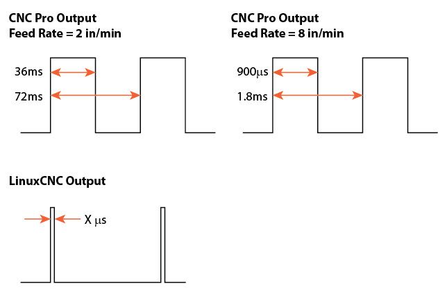
Basically CNC Pro seems to put out a square wave whose frequency (Step Space?) is twice that of the "Step Time". If I increased the feed rate, I'd still get a square wave but it would be shorter in duration and frequency (see images above)
With LinuxCNC, I got a waveform as shown in the bottom image. The frequency would change with feed rate, but the signal width would not change proportionally to a change in "Step Time". I was trying to adjust the StepConf settings to match the CNC Pro waveform so I could have some place to start, but I couldn't make it happen. I expected that whatever value I put into "Step Time" would be the width of the output signal, but that wasn't always the case. I seemed to only be able to produce three different signal widths: 3us, 5us, and 100us. Here is a table of the values I tried and the associated widths I measured from my scope. Note that though I did change the "Step Space" values, they didn't seem to affect the results, so I'm not including those here:
| Step Time | Measured Width "X" | |||
| 150,000 ns | 100 us | |||
| 100,000 ns | 100 us | |||
| 10,000 ns | 100 us | |||
| 7,000 ns | 100 us | |||
| 6,000 ns | 100 us | |||
| 5,000 ns | 5 us | |||
| 1,500 ns | 3 us | |||
| 1,000 ns | 3 us |
So, after all that, my question is: What the heck am I doing wrong?
 I hope that there is a simple explanation for this - maybe something about parallel port timing or some other hardware configuration - but the fact that I set one value for the signal with and get something totally different doesn't make sense.
I'm totally open to buying some new hardware to make this work. I'm sure my stepper drivers would be seriously outperformed by some of the new Gecko and similar drivers, but the problems I'm dealing with now start before any of my current hardware comes into play.
Thanks for any insights provided. I really want to make this work without having to throw out the whole system and start from scratch.
Regards,
Jeff
Please Log in or Create an account to join the conversation.
- andypugh
-

- Offline
- Moderator
-

- Posts: 23550
- Thank you received: 5018
Basically CNC Pro seems to put out a square wave whose frequency (Step Space?) is twice that of the "Step Time". If I increased the feed rate, I'd still get a square wave but it would be shorter in duration and frequency (see images above)
Have you scoped the "dir" signal too? Is it possible that the pulse train is quadrature?
The step timings that stepconf produces might not be as you expect because it might be being too clever.
With short step times it will use the 'Reset" function, which allows a step for every base period.
It looks like stepconf is clever enough to _not_ configure "reset" for long step times, and so the step time becomes one whole base period.
If you want to experiment more, then look at editing the HAL file direclty by hand between runs.
Even if your drives are _not_ quadrature I think that you ought to see the same step pulse train by setting LinuxCNC to quadrature (step type 2).
The "dir" pin, if it is a direction pin, will still work correctly because of the way quadrature indicates direction.
Docs: www.linuxcnc.org/docs/2.4/html/hal_rtcom...b:Stepgen-Step-Types
Edit the hal file so that
loadrt stepgen step_type=0,0,0
becomes
loadrt stepgen step_type=2,2,2
Please Log in or Create an account to join the conversation.
- CinciJeff
- Offline
- New Member
-
- Posts: 5
- Thank you received: 0
I think I understand what you're saying about the "Reset" function, though I don't have a basis to understand the function's purpose. Can you point to a documentation reference?
I did edit the hal file as you suggested, however LinuxCNC stops with an error, so maybe there is more to change than just that one line? The "Debug file information" is the following:
Can not find -sec MOT -var MOT -num 1
Can not find -sec IO -var IO -num 1
Can not find -sec LINUXCNC -var NML_FILE -num 1
Can not find -sec EMC -var NML -num 1
JS_mill-drill.hal:34: parameter or pin 'stepgen.0.steps.stepspace' not found
9045
FWIW, I tried to enter the modified hal command in the "Show hal Configuration" window, but got an error as well.
I'll continue to try to modify the .hal file, but I don't think I'm on the right track yet.
Thanks for your help.
Please Log in or Create an account to join the conversation.
- andypugh
-
- Offline
- Moderator
-
- Posts: 23550
- Thank you received: 5018
Well, it does seem to be badly documented.I think I understand what you're saying about the "Reset" function, though I don't have a basis to understand the function's purpose. Can you point to a documentation reference?
www.linuxcnc.org/docs/html/hal/parallel_...ml#_using_doublestep
Has a link to a wiki page that doesn't mention it...
The parallel port driver has an option to make a list of pins that should be set back to zero every base-period
What happens is that you call the parport-write function in the base thread, optionally run a few other base-thread tasks, then call the parport-reset function. If enough time has elapsed (specified by the reset time) then it sets the reset list of pins back to zero. If there hasn't been enough time then it waits. While it is waiting absolutely nothing else happens in the whole PC. It is best if you arrange for it to never need to wait.
There is no "stepspace" pin in quadrature mode. Just comment out that line (34). The comment character is #I did edit the hal file as you suggested, however LinuxCNC stops with an error, so maybe there is more to change than just that one line? The "Debug file information" is the following:
JS_mill-drill.hal:34: parameter or pin 'stepgen.0.steps.stepspace' not found
Please Log in or Create an account to join the conversation.
- CinciJeff
- Offline
- New Member
-
- Posts: 5
- Thank you received: 0
As I was thinking about this a question came to mind. Since all I'm doing is scoping the parallel port output with no other hardware connected, and this is all running off of a clean LiveCD install, why would I be seeing the timing issues I reported? I would assume that out of the box, using any one of the pre-defined driver setups, I should expect to see steps of the length specified in the configuration. Thing is I don't. I'm only getting the step lengths shown in my first message, regardless of the setup I choose.
Could there be some sort of hardware issue that's causing this? I feel like I might be barking up the wrong tree.
Please Log in or Create an account to join the conversation.
- PCW
-

- Offline
- Moderator
-
- Posts: 19172
- Thank you received: 5308
stepgen mode depending on the length of the selected step pulse
Other than one setting these timing should work just fine for any normal step/dir
machine since the are as long or longer than requested.
Here's what I think is happening:
You have a base thread period of 100 usec so changes to the
parallel port output bits will be quantized to 100 uSec intervals
except if reset mode is used, however reset mode is only used
for step times of 5 uSec or less by stepconf. This is because reset
mode simple spins while waiting for the step time, burning CPU cycles
and slowing the whole system down.
Step Time Measured Width "X"
150,000 ns 100 us This is a genuine mistake and should be 200 uSec (2 base thread periods)
100,000 ns 100 us Correct
10,000 ns 100 us rounded up to next cycle since stepgen is not in reset mode
7,000 ns 100 us rounded up to next cycle since stepgen is not in reset mode
6,000 ns 100 us rounded up to next cycle since stepgen is not in reset mode
5,000 ns 5 us Stepgen decides 5 usec is fast enough to use reset mode
1,500 ns 3 us 3 uSec is as fast as I/O operations run on your parallel port (reset mode)
1,000 ns 3 us 3 uSec is as fast as I/O operations run on your parallel port (reset mode)
If you want to use reset mode to get better intermediate step length times
(say 10 uSec), you will have to tweak the INI /HAL files directly
Also unless you drives are very odd 100 Usec should at least work (though limited to 5 KHz max step rate)
Please Log in or Create an account to join the conversation.
- CinciJeff
- Offline
- New Member
-
- Posts: 5
- Thank you received: 0
I fiddled with the reset command but after trying several values combined with different step times, I didn't see any difference in the pulse width. What I did find, however, is that I could indeed vary my step width by changing the max jitter. The pulse width turned out to be the max jitter value (max. of 50,000) plus the step time (max. of 500,000) so the widest pulse width I could generate was 550 us. At this point I realized I was getting into territory where CNCPro and my old laptop could function. Since that output is a regular square wave, I just upped the feed rate until I got about 500 us. When I plugged back into my drivers, they functioned perfectly. Now I had something to work with: The same pulse width DID work using the old laptop, but DID NOT work on the Dell Optiplex.
The root cause, I believe, is that the Dell is putting out a 3.3v signal out of the parallel port while the laptop is putting out 4.6v.
I did a bunch of searching and while several other people have had this issue, I never did find a clear solution. My thought at this point is to build some sort of level shifter and put it between the computer and the stepper drivers. I'm no electronics wiz, so my inclination is to brute-force a solution by attaching pull-down resistors to all the parallel port pins, then use a bunch of transistors to send 5v to the driver boards when the pins see the 3.3v signal.
First of all, does this make sense as the root cause?
If so, can you think of a better way to solve it than my method above?
I really appreciate all the help. I feel like I'm close! Thanks!!
Please Log in or Create an account to join the conversation.
- Rick G
-

- Offline
- Junior Member
-

- Posts: 27
- Thank you received: 155
The root cause, I believe, is that the Dell is putting out a 3.3v signal out of the parallel port while the laptop is putting out 4.6v.
If the goal is to get the higher voltage on a parallel port you could just try adding a PCI parallel port card.
You can also search the forum for info on the mode the parallel port is in, it seems that in some cases this can effect the power of the port.
Rick G
Please Log in or Create an account to join the conversation.
- andypugh
-
- Offline
- Moderator
-
- Posts: 23550
- Thank you received: 5018
Neither am I.I'm no electronics wiz,
But I think that pulling-up the pins to 5V might work better.so my inclination is to brute-force a solution by attaching pull-down resistors to all the parallel port pins, then use a bunch of transistors to send 5v to the driver boards when the pins see the 3.3v signal.
If the driver boards inputs are optos then rewiring to have 5V at the top and the p-port connected at the bottom will probably work.
If the inputs aren't optos, then perhaps add some instead of the transistors you were talking about?
Please Log in or Create an account to join the conversation.
- CinciJeff
- Offline
- New Member
-
- Posts: 5
- Thank you received: 0
Bottom line is that I did indeed need the 5v signals. I initially tested it out with an ultra-simple Arduino program to test one axis. That worked, so I talked to a EE friend of mine and he put together a few components to make a level-shifter for me. It's currently a rat's nest on a breadboard, but it works!
Long-term I'll look for a dedicated IC to do the shift for me, but at least I'm up and running. Now I can concentrate on learning the software and making chips!
Thanks again for all the help.
Please Log in or Create an account to join the conversation.