Parallel limit switch connection problem
- caseyryan
- Offline
- New Member
-

- Posts: 11
- Thank you received: 0
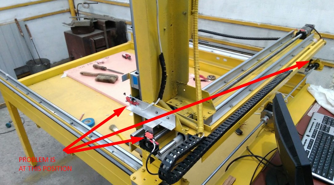
I tried to connect limit switches in parallel, so they could all work as one but after I had connected everything and tested I bumped into a problem I haven't managed to find solution for.
The problem is that when the router bumps into one of the switches it throws an error saying "can't jog joint 0 further past max hard limit". I've googled some pages with similar problems but to no avail so far.
The switches are connected in my .hal file like so:
net XYZ-max-lim parport.0.pin-12-in-not => axis.0.pos-lim-sw-in axis.1.pos-lim-sw-in axis.2.pos-lim-sw-inI've also attached the picture of .INI file of my router config (sorry, I wasn't able to get the file itself for there were some problems with copying it to a flashcard).
What am I doing wrong? Is there a way to change this behavior?
Right now the only way to get the router off the switch is to manually disconnect the
Please Log in or Create an account to join the conversation.
- DanMN
-

- Offline
- Senior Member
-

- Posts: 74
- Thank you received: 10
Please Log in or Create an account to join the conversation.
- caseyryan
- Offline
- New Member
-

- Posts: 11
- Thank you received: 0
Well, if I understand you correctly, you mean the entire switching loop must always be high unless one of the switches breaks it. If so, it absolutely doesn't matter. I tied both configurations with high and low pins. It gives me the same error in both cases.Since you're using a "not" pin, that would imply you'll need to create a wiring loop that is normally closed and pulls the pin high until any of the switches is opened by axis travel limit contact.
I can't provide a separate pin for each switch because I only have 4 of them on my board, and one of them is used for a tool touch-off plate. But in this case it wouldn't even change anything whether I connect 3 axes separately or just as one switch. The router would just get stuck every time it reaches 0:0:0 position on any axis. I believe there must be some programmatic solution to this.
All I want is the router to stop when it bumps into any of the switches and then be able to jog it back again by checking "override limits" box. At the moment I can only do it if it hits any switch on the other side of the router frame
What does this "hard limit" mean? And why does it need it at all?
Please Log in or Create an account to join the conversation.
- DanMN
-

- Offline
- Senior Member
-

- Posts: 74
- Thank you received: 10
Please Log in or Create an account to join the conversation.
- caseyryan
- Offline
- New Member
-

- Posts: 11
- Thank you received: 0
So, how can I resolve this? Change the homing offset to some negative value, like, say -10?you're instructing the axis to go backward to zero from home offset after finding the switch
p.s. It was not my setup, most of this is the default configuration of linuxcnc, including the homing offset of 5 (I didn't even know what it meant until you told me)
Please Log in or Create an account to join the conversation.
- DanMN
-

- Offline
- Senior Member
-

- Posts: 74
- Thank you received: 10
Please Log in or Create an account to join the conversation.
- caseyryan
- Offline
- New Member
-

- Posts: 11
- Thank you received: 0
I haven't even set up homing sensors (it still is another matter to learn to me), for now I only want to be able to jog the router off of the limit switch by means of software.
I think you would agree that any machine has its hard limits on both sides. Going in any direction it might drive itself onto the floor if it isn't stopped by a limit switch or some other safety device. But I just can't get the idea of making it possible to override the limits on one side and making it impossible on the other. It really looks weird to me when my router gets stopped by a limit switch and then I have to turn it off, reach it and rotate the stepper motor by hand to make it jog off the switch.
Will the negative homing offset resolve this problem?
Please Log in or Create an account to join the conversation.
- Mike_Eitel
-

- Offline
- Platinum Member
-

- Posts: 1052
- Thank you received: 183
1. Have a reading session.
www.linuxcnc.org/docs/devel/html/config/ini-homing.html.
for master branch or
www.linuxcnc.org/docs/2.7/html/config/ini-homing.html
if you in 2.7 branch.
2. You must home one axis after the other. The order is defined by HOME_SEQUENCE
3. After one axis has found it's zero you have to send it to a position where "his" switch is no more active. By HOME=xxx.
4. Then the next axis is free to run...
Mike
Please Log in or Create an account to join the conversation.
- DanMN
-

- Offline
- Senior Member
-

- Posts: 74
- Thank you received: 10
If you take this orientation as correct, you need to configure something like this (presuming 1000 mm travel for example):
X Axis:
Your HOME SEARCH VELOCITY is a positive number
Your HOME OFFSET is 995
Your HOME is 5
This gives you 990mm of travel inside of soft limits. Your homing cycle will narrate as:
"Move in the positive direct of Y at HOME SEARCH VELOCITY until you encounter the switch. Back off the switch at HOME LATCH VELOCITY (a negative number in your case, since the sign needs to be opposite from SEARCH velocity), once you've barely creeped backward off the switch, define that exact point as the 995mm positive soft limit of the machine. Now, move backward 990mm to a point which is physically 5mm from the hard end of travel, and name that point axis soft limit ZERO."
So, you've turned the machine on, hit "Home" and this should happen if configured sanely:
1. Your z-axis (ideally homing at the TOP of its travel, with HOME_SEQUENCE = 0!) moves up as far as it can go before the other axes move. This will prevent a lot of snapped tools and gouged tables...
2. Your other two axes are defined with HOMING_SEQUENCE = 1 and 2 respectively, and each in turn finds it's limit switch, latches and moves to HOME.
In my case, my table homes at the operator end. When I hit Home, the spindle lifts, latched and stops, then the X-axis moves to the left, latches and stops, then the Y-axis moves in the negative direction toward me until it finds the switch and latches. As soon a Y-latches, both the X and Y simultaneously move to HOME -- which in my case is the midpoint of each axis.
Please Log in or Create an account to join the conversation.
- DanMN
-

- Offline
- Senior Member
-

- Posts: 74
- Thank you received: 10
If you simply want to fake your machine into overriding a tripped switch you could temporarily wire in momentary contact switch to make or break your loop. I did that during the configuration stage until I had wrapped my head around the concepts involve.
Please Log in or Create an account to join the conversation.


