- Configuring LinuxCNC
- Configuration Tools
- StepConf Wizard
- [SOLVED] Stepper motors not showing any sign of life
×
Forum Header
[SOLVED] Stepper motors not showing any sign of life
- TrapCat
- Offline
- New Member
-

Less
More
- Posts: 3
- Thank you received: 2
22 Dec 2020 20:37 - 23 Dec 2020 08:30 #192859
by TrapCat
[SOLVED] Stepper motors not showing any sign of life was created by TrapCat
Hey everyone, glad to be joining this community.
Issue: can't manage to get the motors moving or holding position (basically they are in the same state as when powered off)
I've recently bought some used material to start building my first CNC and today I ran into some issues testing the electronics.
I'm sure that everything is in working condition because the previous owner showed me the motors working although he was using MACH3.
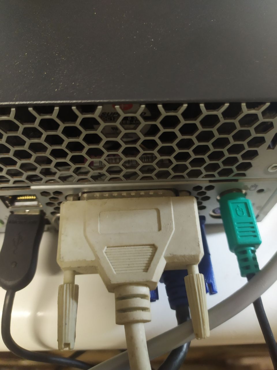
I've installed LinuxCNC on an old desktop computer that had a parallel port without any issues. Hooked up the parallel cable and USB cable that came with the electronics, leaving all the pre-existing connections between the BoB, drivers and motors untouched.
Then I ran the StepConf Wizard, changed units, selected "other" for the driver type (leaving all the default parameters being 5000,5000,20000,20000 for step time, space, direction hold, setup) because I couldn't find any information online about my drivers. I then ran the jitter test and copied the max value in the box.
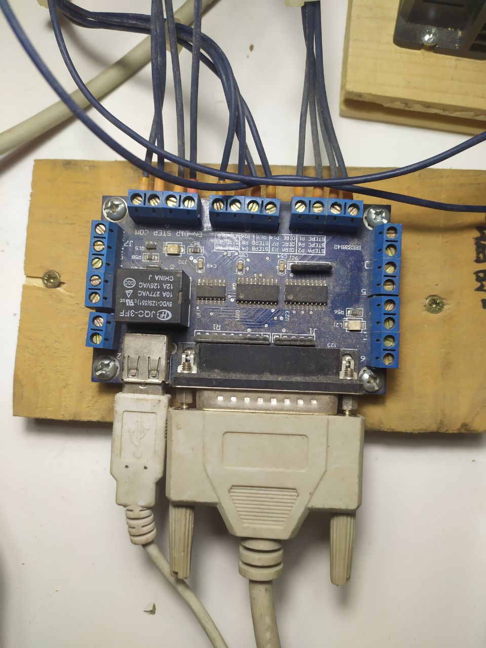
I then copied the pinout specified for my BoB but only for the motors STEP and DIR setting anything else to "unused", wanting to only test the motors:
-Pin 2: X Step
-Pin 3: X Dir
-Pin 4: Y Step
-Pin 5: Y Dir
-Pin 6: Z Step
-Pin 7: Z Dir
I then proceeded to the different axis configuration pages and, just setting steps per revolution and microsteps (looking at the tiny switches pre-set by the previous owner), I hit "test this axis". Here is the problem. All I got, for each axis, was a really brief flash of an LED on the BoB and at the same time the on-board relay clicking, nothing else. None of the motors moved or seemed to oppose any resistance to being twisted by hand.
After trying to change different parameters making different configurations (inverting the pins, changing steps per revolution and the timings on the first configuration page) the result was always the same, relay and LED briefly activating when clicking on "test" and nothing else.
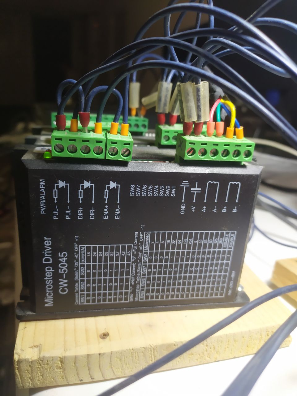
Afterwards I tried checking the connections and found that the ENA+, DIR+ and PUL+ where all tied to the BoB COM, while ENA-, DIR- and PUL- where all connected to the respectively labeled pins on the BoB. Measuring from COM to ENA-, DIR- and PUL- i got around 4.5V.
I also tried inverting the connections (connecting the +s to the respective pins and the -s to COM) but got the exact same result.
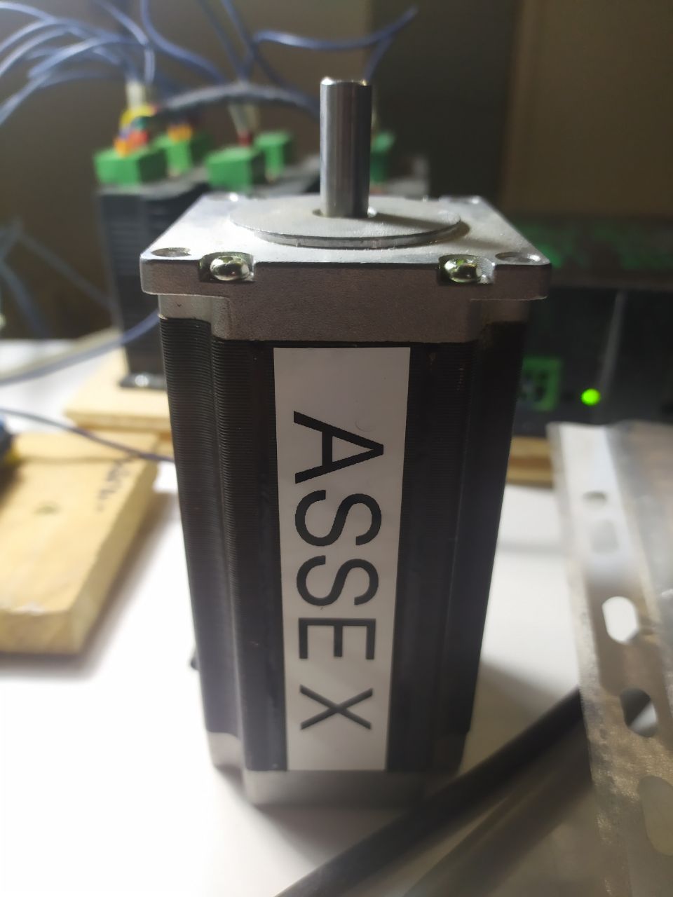
I'll attach some pictures of the BoB (I know it's dirty but it's just superficial), driver and motor:
Thanks to all of you in advance, in case you need more infos I'll send them asap.
Happy CNCing
Issue: can't manage to get the motors moving or holding position (basically they are in the same state as when powered off)
I've recently bought some used material to start building my first CNC and today I ran into some issues testing the electronics.
I'm sure that everything is in working condition because the previous owner showed me the motors working although he was using MACH3.
I've installed LinuxCNC on an old desktop computer that had a parallel port without any issues. Hooked up the parallel cable and USB cable that came with the electronics, leaving all the pre-existing connections between the BoB, drivers and motors untouched.
Then I ran the StepConf Wizard, changed units, selected "other" for the driver type (leaving all the default parameters being 5000,5000,20000,20000 for step time, space, direction hold, setup) because I couldn't find any information online about my drivers. I then ran the jitter test and copied the max value in the box.
I then copied the pinout specified for my BoB but only for the motors STEP and DIR setting anything else to "unused", wanting to only test the motors:
-Pin 2: X Step
-Pin 3: X Dir
-Pin 4: Y Step
-Pin 5: Y Dir
-Pin 6: Z Step
-Pin 7: Z Dir
I then proceeded to the different axis configuration pages and, just setting steps per revolution and microsteps (looking at the tiny switches pre-set by the previous owner), I hit "test this axis". Here is the problem. All I got, for each axis, was a really brief flash of an LED on the BoB and at the same time the on-board relay clicking, nothing else. None of the motors moved or seemed to oppose any resistance to being twisted by hand.
After trying to change different parameters making different configurations (inverting the pins, changing steps per revolution and the timings on the first configuration page) the result was always the same, relay and LED briefly activating when clicking on "test" and nothing else.
Afterwards I tried checking the connections and found that the ENA+, DIR+ and PUL+ where all tied to the BoB COM, while ENA-, DIR- and PUL- where all connected to the respectively labeled pins on the BoB. Measuring from COM to ENA-, DIR- and PUL- i got around 4.5V.
I also tried inverting the connections (connecting the +s to the respective pins and the -s to COM) but got the exact same result.
I'll attach some pictures of the BoB (I know it's dirty but it's just superficial), driver and motor:
Thanks to all of you in advance, in case you need more infos I'll send them asap.
Happy CNCing
Last edit: 23 Dec 2020 08:30 by TrapCat.
Please Log in or Create an account to join the conversation.
- Todd Zuercher
-

- Offline
- Platinum Member
-

Less
More
- Posts: 4753
- Thank you received: 1458
22 Dec 2020 21:37 - 22 Dec 2020 21:41 #192868
by Todd Zuercher
Replied by Todd Zuercher on topic Stepper motors not showing any sign of life
You most likely need to configure the enable signal. Not sure which parallel port pin it is connected to on that board (there is a glare in the photo and can't read that part.) Best guess it's pin-17. Set it up in Stepconfig. You may or may not have to invert the signal. It probably won't work in the test screen of Stepconfig because I don't think it uses the enable.
You might also need to connect a jumper on the left side of the board to enable the BOB.
You might also need to connect a jumper on the left side of the board to enable the BOB.
Last edit: 22 Dec 2020 21:41 by Todd Zuercher.
The following user(s) said Thank You: TrapCat
Please Log in or Create an account to join the conversation.
- tommylight
-

- Online
- Moderator
-

Less
More
- Posts: 21692
- Thank you received: 7414
22 Dec 2020 21:41 #192870
by tommylight
Replied by tommylight on topic Stepper motors not showing any sign of life
Yank out the enable connectors, set the pins as described on the BOB, not standard pinout, so use step/dir A, step/dir B and step/dir C.
Report back.
Report back.
The following user(s) said Thank You: TrapCat
Please Log in or Create an account to join the conversation.
- TrapCat
- Offline
- New Member
-
Less
More
- Posts: 3
- Thank you received: 2
22 Dec 2020 21:57 #192877
by TrapCat
Replied by TrapCat on topic Stepper motors not showing any sign of life
Thank you so much for your quick answers, tomorrow morning I'll try your suggestions and report back because now it's a bit late.
The following user(s) said Thank You: tommylight
Please Log in or Create an account to join the conversation.
- TrapCat
- Offline
- New Member
-
Less
More
- Posts: 3
- Thank you received: 2
23 Dec 2020 08:29 #192934
by TrapCat
Replied by TrapCat on topic Stepper motors not showing any sign of life
[SOLVED]
Fix: setting pin 17 (as stated on the BoB) as "Amplifier Enable" during the StepConf (even worked with the "test" button so it uses the enable)
Guys thank you SO MUCH, your suggestions worked. I'm so happy right now, I love the fact that communities like this exist.
Happy CNCing everyone and have a great day.
The following user(s) said Thank You: tommylight
Please Log in or Create an account to join the conversation.
- Configuring LinuxCNC
- Configuration Tools
- StepConf Wizard
- [SOLVED] Stepper motors not showing any sign of life
Time to create page: 0.557 seconds