- Configuring LinuxCNC
- Configuration Tools
- StepConf Wizard
- Only getting 1/5th the distance for axis travel.
Only getting 1/5th the distance for axis travel.
- afkool
- Offline
- New Member
-

- Posts: 6
- Thank you received: 0
nema 17 stepper motors 1.8deg
1.25mm pitch leadscrews
cncgeeker.com's 3 axis board TB6560 has 1, 1/2, 1/8, 1/16 microstep resolution (set for 1/8)
I just can't seem to get it to be the correct distance. I even tried setting to microsteps on the driver to 1 because that was the complete opposite setting for dip switches, figured I might be reading them upside or something.
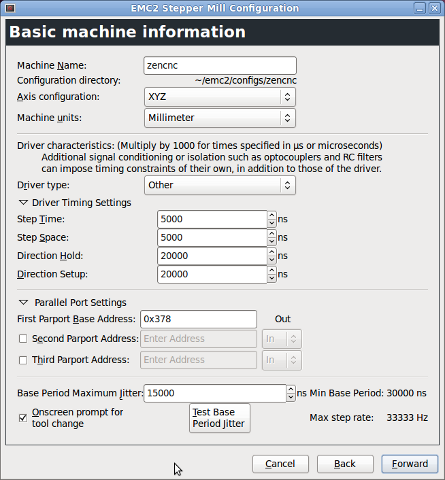
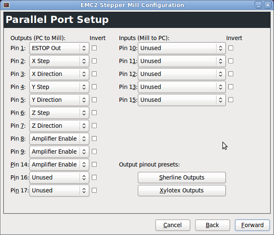
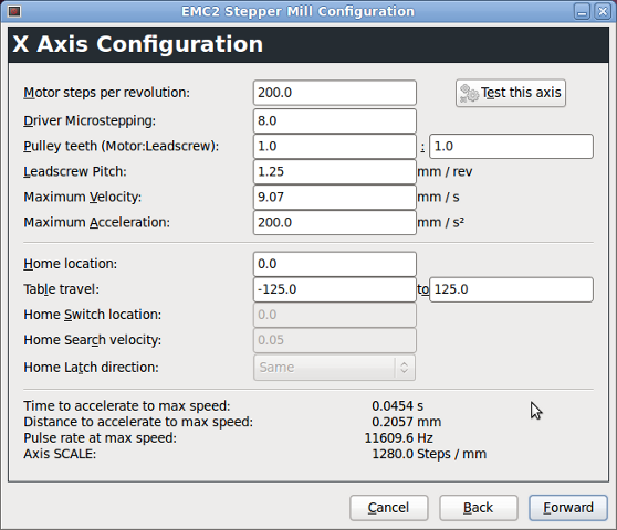
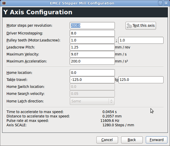
Here are my configuration screens.

Help would be greatly appreciated I'm racking my brain trying to get this to work.
Thanks
Antoni
Please Log in or Create an account to join the conversation.
- Rick G
-

- Offline
- Junior Member
-

- Posts: 27
- Thank you received: 155
After using Stepconfig to create the proper setup I often just go into my configuration file and edit the scale to get the right movement.
Rick G
Please Log in or Create an account to join the conversation.
- BigJohnT
-

- Offline
- Administrator
-

- Posts: 6999
- Thank you received: 1177
You don't mention if your steppers are directly connected to your lead screw or via a reduction belt.
For testing I put a mark on my stepper shaft and make sure I know how many steps it takes to get one rev on the stepper... then go from there.
John
Please Log in or Create an account to join the conversation.
- afkool
- Offline
- New Member
-
- Posts: 6
- Thank you received: 0
BigJohnT wrote:If you are off by 1/5 try just changing the pulley setting to 1 to 5.
After using Stepconfig to create the proper setup I often just go into my configuration file and edit the scale to get the right movement.
Rick G
Just like Rick I just change the scale number to be what I need.
Does this scale effect the hardware communication? I guess I'm just asking if I will have to slow down my total speed to avoid missing steps or if this is just internal to the software so to get 5x scale it sends 5x steps over 5x the time? Not 5x the steps in the same amount of time.
BigJohnT wrote:
Just like Rick I just change the scale number to be what I need. All the other numbers don't mean anything only the Axis SCALE: number is used. So it looks like yours needs to be 256 or there about. But that number does not sound right for 200 steps a rev at 1/8 microstepping and 1.25mm pitch for a direct connection.
You don't mention if your steppers are directly connected to your lead screw or via a reduction belt.
For testing I put a mark on my stepper shaft and make sure I know how many steps it takes to get one rev on the stepper... then go from there.
John
Sorry, my steppers are directly connected to the lead screw. How did you go about testing how many steps it takes to get one rev? I'm curious if you did it through software or some kind of manual wiring?
Thanks for your help.
Please Log in or Create an account to join the conversation.
- BigJohnT
-
- Offline
- Administrator
-
- Posts: 6999
- Thank you received: 1177
I just put a mark on the shaft or somewhere and if I expect a move of 1.25 to be one revolution I just issue a feed move of 1.25 at a slow feed rate and observe the shaft of the stepper and see if the mark makes one full revolution. I do this in Axis but I think you can do it in the "Test this Axis" of stepconf.
John
Please Log in or Create an account to join the conversation.
- afkool
- Offline
- New Member
-
- Posts: 6
- Thank you received: 0
I've done some more testing with this. I tried issuing movements in axis and it was not correct. I then decided to start rulling out my pc hardware. So I used a different pc. This time I used windows 7 and mach3. I actually ended up with the same results??? The scale was still off.
So I decided to test the other side of it; the driver hardware. I wrote up a little program on an arduino I had lying around. It pins out directly to the driver controller. Wrote up a little serial interface where I can set settings like steps, frequency, and hold time. Then enable and run an axis. Turns out....It's dead on. I set the driver board for 1:1 microsteps and it worked fine. 200 steps moved it around 360deg, 400 steps for 1:2, 1600 for 1:8 etc. I then hooked up my dial indicator and stepped it 1280 when it was micro stepped for 1:8. It moved 1mm as expected.
(actually if anyone is interested, I'm thinking about open sourcing this [simple] code out on google source for other people's testing)
I must be doing some wrong with the software config. I just don't know what it is. I'm even using the same parallel cable. I'm gonna go through it again I guess.
Please Log in or Create an account to join the conversation.
- Rick G
-
- Offline
- Junior Member
-
- Posts: 27
- Thank you received: 155
I go to mdi and issue a command for say a .10 inch move and note the amount the machine moves. Like John said make this a slow move so you can see what is going on.
Take the results scale =xxx and movement was .xxx" do the math and enter the correct scale, then test again.
Rick G
Please Log in or Create an account to join the conversation.
- afkool
- Offline
- New Member
-
- Posts: 6
- Thank you received: 0
I understand that I can correct the steps/mm axis scale to fine tune everything. However it's still 5x off. That seems like a huge number to indicate that something is not right and it's obviously pc/setup related.
Please Log in or Create an account to join the conversation.
- andypugh
-

- Offline
- Moderator
-

- Posts: 23543
- Thank you received: 5015
First, can you measure the voltages on the parallel port when stepping? A scope would be best, but that Arduino has some nice anaolgue inputs.
How do you have the P-port wired to the drives? Generally a P-port can sink a lot more current than it can source. Many ports are only 3.3V. A 1k pull-up resistor to 5V (which you can source from a USB port) might help to firm up the signals.
This diagram here shows a typical scheme (except it is wired to some logic chips, rather than stepper drivers)
Do the drives have an opto-coupled input? If so then the way to wire is with +5V to the + side of the input, and the p-port to the - side, then current flows through the opto when the port pin goes low, activating the input.
Please Log in or Create an account to join the conversation.
- cncbasher
- Offline
- Moderator
-
- Posts: 1744
- Thank you received: 288
try slowing down the velocity and acceleration , it could well be a combination of one or both .
i would also reduce your microsteps to 1/2 or 1/4 to start with , easier to find the problem and then increase later , although i do not see any benefit running greater than 1/2 step , with your table setup , as your driving the shaft directly .
Dave
Please Log in or Create an account to join the conversation.
- Configuring LinuxCNC
- Configuration Tools
- StepConf Wizard
- Only getting 1/5th the distance for axis travel.