A Simple Parallel Port Tester Board
- ContinenteCNC
-
 Topic Author
- Offline
- Premium Member
-

Less
More
- Posts: 97
- Thank you received: 44
31 Mar 2025 18:23 - 31 Mar 2025 18:54 #325421
by ContinenteCNC
A Simple Parallel Port Tester Board was created by ContinenteCNC
I wanted an easier way to test a new PCI parallel port card in all three modes (OUT, IN and X) in order to help with this topic here:
forum.linuxcnc.org/18-computer/54368-pci...-work-out-of-the-box
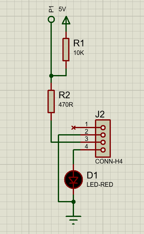
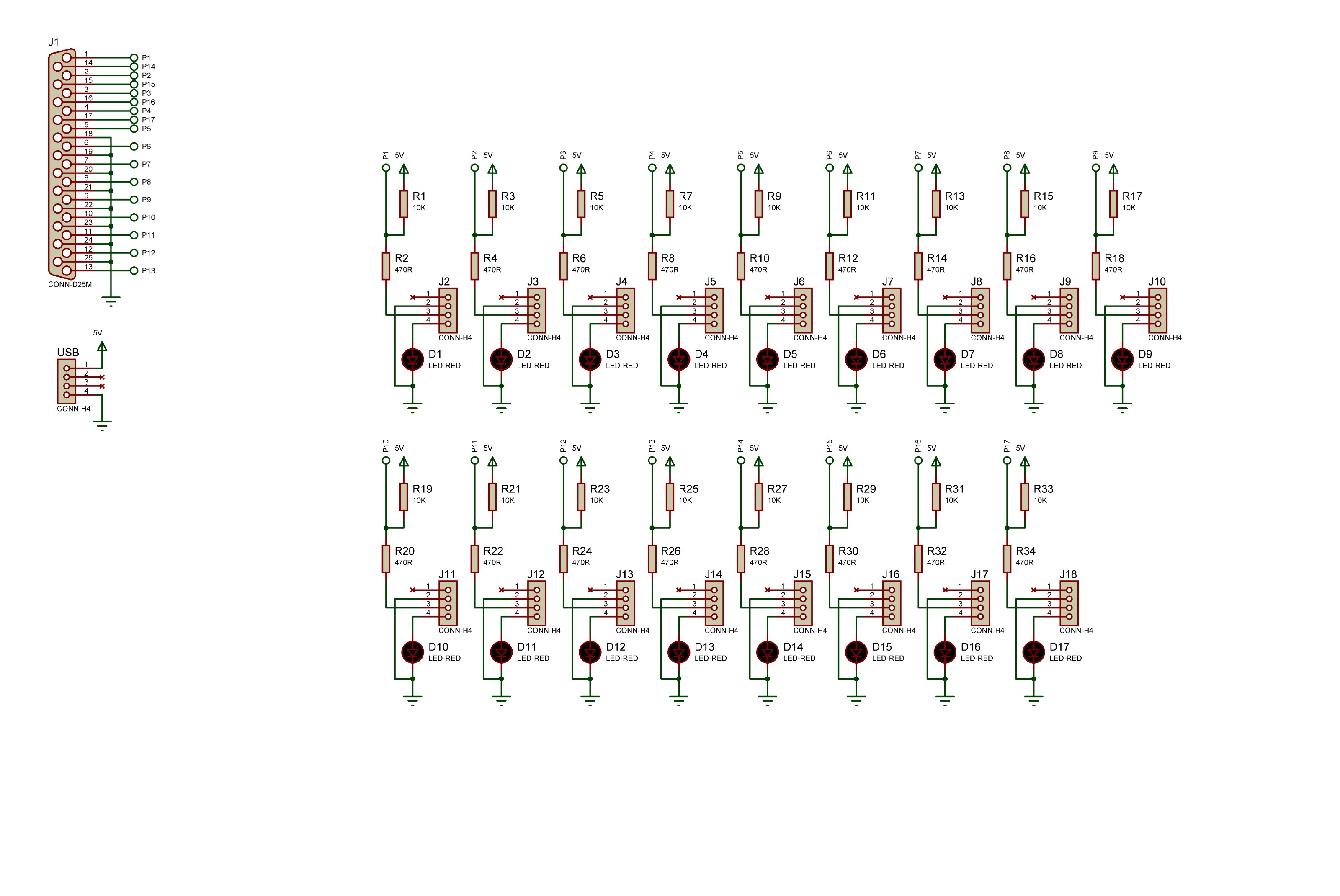
So I came up with this simple, yet "powerful", parallel port test board. The core circuit for each pin is very simple and uses only 4 components. No IC and no transistors required.
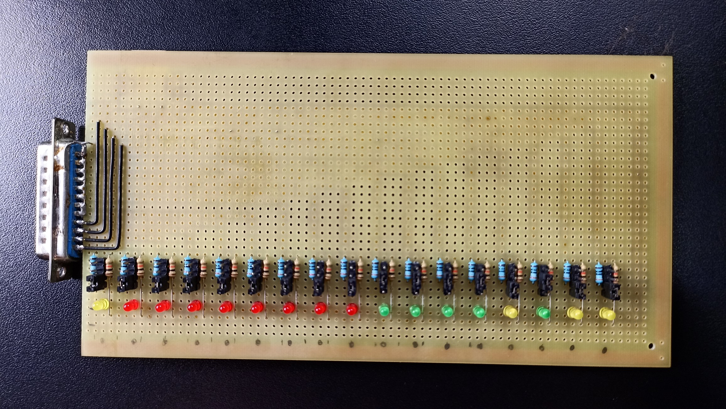
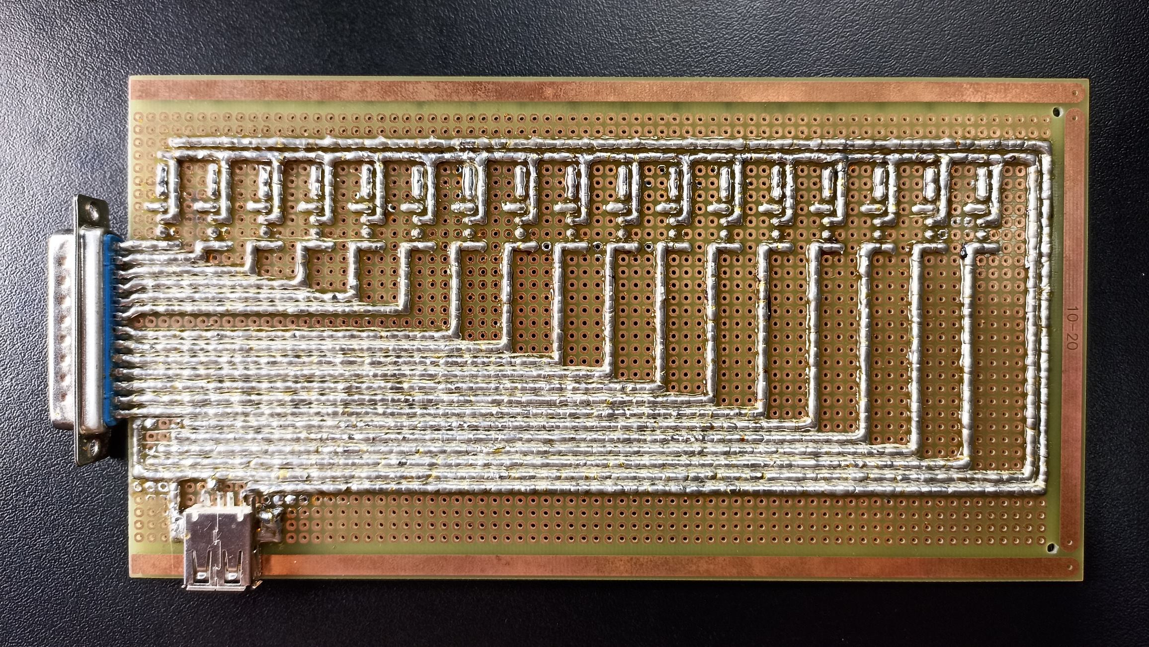
Every single pin can be tested as input and output. It is passive (no buffer) but I have also added a USB conector to provide 5 volts to 10k pull-up resistors (some cards won't have pull-up resistors for every pin). I used different color LEDs to represent each register: Red for Data, Green for Status and Yellow for Control. However I would suggest not to use yellow LEDs because they are not as bright as red and green ones.
It is handy to diagnose single damaged pins. Sometimes a given card has only one or two damaged pins and maybe they have got only input side damage (I have never seen this last case, but I believe it can happen). So you can swap pins positions knowing in advance what is still working.
(Btw, if parallel port masters here could suggest better values for resistors I'd be happy. Maybe 20k for pull-ups? I know some cards require more current to trigger control register pins when working in X mode, so maybe 490 ohms would be too high. But I also don't wan't to destroy non open-collector pins while investigating a unkkown card in X mode)
I didn't have any three position switches laying around, so I used four pin headers instead.
I will be making a single layer PCB version soon.
As it is:
The LOWER position sets pin as OUTPUT and the led will lightup if STATE = HIGH
The MIDDLE position sets pin as INPUT with STATE = LOW (0 volts through 490 ohms resistor)
The UPPER position sets pin as INPUT with STATE = HIGH (it is actually connected to nothing, so it will just let the 10k pull-up resistor do it's job)
(I know, if one single atom of iron gets between this traces the will short circuit, but I had take as much time as possible to assemble it, so my wife wouldn't ask me to rearrange forniture... I also find it terapeutical to join blobs of solder, ONCE you learn the proper technique)
Last edit: 31 Mar 2025 18:54 by ContinenteCNC.
The following user(s) said Thank You: tommylight
Please Log in or Create an account to join the conversation.
- tommylight
-

- Away
- Moderator
-

Less
More
- Posts: 21291
- Thank you received: 7267
31 Mar 2025 19:49 #325423
by tommylight
Replied by tommylight on topic A Simple Parallel Port Tester Board
I have this
forum.linuxcnc.org/39-pncconf/32400-mesa...pport?start=60#89231
A box with 17 resistors and 17 LED's, a male and a f-male port, nothing else.
Not versatile as yours, but it has also the option of connecting between the PC and machine and monitor in real time.
forum.linuxcnc.org/39-pncconf/32400-mesa...pport?start=60#89231
A box with 17 resistors and 17 LED's, a male and a f-male port, nothing else.
Not versatile as yours, but it has also the option of connecting between the PC and machine and monitor in real time.
The following user(s) said Thank You: ContinenteCNC
Please Log in or Create an account to join the conversation.
- ContinenteCNC
-
 Topic Author
- Offline
- Premium Member
-

Less
More
- Posts: 97
- Thank you received: 44
01 Apr 2025 00:32 - 01 Apr 2025 00:33 #325434
by ContinenteCNC
Replied by ContinenteCNC on topic A Simple Parallel Port Tester Board
The option of connecting between PC and machine sounds interesting.
What resistor size have you used?
What resistor size have you used?
Last edit: 01 Apr 2025 00:33 by ContinenteCNC.
Please Log in or Create an account to join the conversation.
- tommylight
-

- Away
- Moderator
-

Less
More
- Posts: 21291
- Thank you received: 7267
01 Apr 2025 00:42 #325436
by tommylight
Replied by tommylight on topic A Simple Parallel Port Tester Board
No idea, but i am i sure i had 330, 470 and 680 Ohm ones at the time i built it probably over 10 years ago.
The following user(s) said Thank You: ContinenteCNC
Please Log in or Create an account to join the conversation.
- ContinenteCNC
-
 Topic Author
- Offline
- Premium Member
-

Less
More
- Posts: 97
- Thank you received: 44
01 Apr 2025 22:44 #325489
by ContinenteCNC
Replied by ContinenteCNC on topic A Simple Parallel Port Tester Board
I believe I can add this option to my circuit as well. I just have to add a output connector and set all pins to output.
When I find time to design the PCB I will include this feature.
When I find time to design the PCB I will include this feature.
Please Log in or Create an account to join the conversation.
Time to create page: 0.130 seconds


