- Hardware & Machines
- Computers and Hardware
- 4-Gang 1-Way Switch To Control 3 Power Supplies and a Router Independently
4-Gang 1-Way Switch To Control 3 Power Supplies and a Router Independently
- behai
- Offline
- Senior Member
-

Less
More
- Posts: 56
- Thank you received: 17
04 Apr 2025 12:14 #325681
by behai
4-Gang 1-Way Switch To Control 3 Power Supplies and a Router Independently was created by behai
Hi,
Please help me with the following question regarding a 4-gang 1-way switch to turn on and off 3 power supplies and a router independently.
I would like to set up the circuits in the below diagram:

I am from Melbourne, Victoria, Australia, we are on 240V and 10A.
The 3 power supplies are:
1. 5V 2A ( I already have ): to power my Mesa 7I96S card.
2. 24V 4A ( I already have ): to power the proximity switches.
3. 36V, 800W, 22+A ( I don't have yet ): to power the 4 stepper drivers CL57T-V41 and 4 Nema 23 stepper motors.
4. To power a router to use with the CNC machine.
With a 4-gang 1-way switch, I am able to independently turn on and off any devices I see fit.
If an emergency happens, I will just press the emergency switch and all 4 circuits will just turn off.
I have also the emergency switch, and I've learned how to wire it, I have been able to test the wiring successfully using a microwave fan.
PLEASE HELP:
1. Is this an appropriate set up, please?
2. If (1) is an appropriate set up, can you help recommending a correct 4-gang 1-way switch, please?
I am only able to find light switches, for example:
directwholesale.com.au/products/clipsal-...-white/?gad_source=1
Clipsal Switch 4 Gang 10A Pvc Square Plt White - P2034/2VA-WE
$72.50
And I am not sure if they will work for this set up.
I understand the potential dangers. If it is appropriate and I know of the switch, then I have something to do further studies. I take full responsiblities for what I am doing.
Thank you and best regards,
...behai.
Please help me with the following question regarding a 4-gang 1-way switch to turn on and off 3 power supplies and a router independently.
I would like to set up the circuits in the below diagram:
I am from Melbourne, Victoria, Australia, we are on 240V and 10A.
The 3 power supplies are:
1. 5V 2A ( I already have ): to power my Mesa 7I96S card.
2. 24V 4A ( I already have ): to power the proximity switches.
3. 36V, 800W, 22+A ( I don't have yet ): to power the 4 stepper drivers CL57T-V41 and 4 Nema 23 stepper motors.
4. To power a router to use with the CNC machine.
With a 4-gang 1-way switch, I am able to independently turn on and off any devices I see fit.
If an emergency happens, I will just press the emergency switch and all 4 circuits will just turn off.
I have also the emergency switch, and I've learned how to wire it, I have been able to test the wiring successfully using a microwave fan.
PLEASE HELP:
1. Is this an appropriate set up, please?
2. If (1) is an appropriate set up, can you help recommending a correct 4-gang 1-way switch, please?
I am only able to find light switches, for example:
directwholesale.com.au/products/clipsal-...-white/?gad_source=1
Clipsal Switch 4 Gang 10A Pvc Square Plt White - P2034/2VA-WE
$72.50
And I am not sure if they will work for this set up.
I understand the potential dangers. If it is appropriate and I know of the switch, then I have something to do further studies. I take full responsiblities for what I am doing.
Thank you and best regards,
...behai.
Please Log in or Create an account to join the conversation.
- tommylight
-

- Away
- Moderator
-

Less
More
- Posts: 21728
- Thank you received: 7425
04 Apr 2025 12:32 #325683
by tommylight
Replied by tommylight on topic 4-Gang 1-Way Switch To Control 3 Power Supplies and a Router Independently
Seems a bit excessive and not very useful.
It is much better to use a single small industrial switch and 4 of automatic fuses inside the control box, you can switch on/off automatic fuses as they can handle a bit of torture although they are not made for it, but since they will be used during testing only, they will be fine.
It is much better to use a single small industrial switch and 4 of automatic fuses inside the control box, you can switch on/off automatic fuses as they can handle a bit of torture although they are not made for it, but since they will be used during testing only, they will be fine.
The following user(s) said Thank You: behai
Please Log in or Create an account to join the conversation.
- unknown
- Offline
- Platinum Member
-

Less
More
- Posts: 888
- Thank you received: 325
04 Apr 2025 13:55 #325686
by unknown
Replied by unknown on topic 4-Gang 1-Way Switch To Control 3 Power Supplies and a Router Independently
I probably when OTT with power supplies.
What I did was use some light weight DPDT relays, one set of contacts latches the relay after briefly being energised by a pushbutton and the other set of contacts controls a contactor with a 24v coil. I find this a great because if the power is removed, blackout breaker tripping, and comes back on the power doesn't come back on.
I went with a relay > contactor setup as I wanted to keep the 240 seperated from the 24v control. The only issue is that there is an always on 24v supply dedicated to the relays.
To clarify there's one relay/contactor per power supply. Each power supply can be independently controlled. For wiring the latching relay I had some PCBs made to simplify the wiring.
Bit more involved than a 4 way gang switch. The same thing could be implemented with a NVR switch for each PSU.
Oh I forgot I'm series with each pushbutton is another switch, this is used to turn the relay off and has to be in the "on" position before pushing the button to turn the power supply on. It's kind of like starting a rocket.
The following user(s) said Thank You: behai
Please Log in or Create an account to join the conversation.
- unknown
- Offline
- Platinum Member
-
Less
More
- Posts: 888
- Thank you received: 325
04 Apr 2025 16:32 #325694
by unknown
Replied by unknown on topic 4-Gang 1-Way Switch To Control 3 Power Supplies and a Router Independently
Thought I'd better add a picture.
One set per 240v line you need to switch.
One set per 240v line you need to switch.
Attachments:
The following user(s) said Thank You: behai
Please Log in or Create an account to join the conversation.
- behai
- Offline
- Senior Member
-
Less
More
- Posts: 56
- Thank you received: 17
05 Apr 2025 04:35 #325742
by behai
Replied by behai on topic 4-Gang 1-Way Switch To Control 3 Power Supplies and a Router Independently
Thank you @tommylight and @unknown ( Rob ),
I appreciate your suggestions. I have learned of this set up from this YouTube video from the thehardwareguy channel.
Please see from 5:40 to 07:50 -- he uses a 2-gang switch, even though he has 2 PSU and 1 VFD.
Best regards,
...behai.
I appreciate your suggestions. I have learned of this set up from this YouTube video from the thehardwareguy channel.
Please see from 5:40 to 07:50 -- he uses a 2-gang switch, even though he has 2 PSU and 1 VFD.
Best regards,
...behai.
Please Log in or Create an account to join the conversation.
- behai
- Offline
- Senior Member
-
Less
More
- Posts: 56
- Thank you received: 17
05 Apr 2025 04:41 #325743
by behai
Hi Rob,
Thank you very much for your explanations. The first solution is way over my head")
I am going to study the NVR switch. They look better than 4-gang switches and more accessible, too.
Best regards,
...behai.
Replied by behai on topic 4-Gang 1-Way Switch To Control 3 Power Supplies and a Router Independently
I probably when OTT with power supplies.
What I did was use some light weight DPDT relays, one set of contacts latches the relay after briefly being energised by a pushbutton and the other set of contacts controls a contactor with a 24v coil. I find this a great because if the power is removed, blackout breaker tripping, and comes back on the power doesn't come back on.
I went with a relay > contactor setup as I wanted to keep the 240 seperated from the 24v control. The only issue is that there is an always on 24v supply dedicated to the relays.
To clarify there's one relay/contactor per power supply. Each power supply can be independently controlled. For wiring the latching relay I had some PCBs made to simplify the wiring.
Bit more involved than a 4 way gang switch. The same thing could be implemented with a NVR switch for each PSU.
Oh I forgot I'm series with each pushbutton is another switch, this is used to turn the relay off and has to be in the "on" position before pushing the button to turn the power supply on. It's kind of like starting a rocket.
Hi Rob,
Thank you very much for your explanations. The first solution is way over my head
I am going to study the NVR switch. They look better than 4-gang switches and more accessible, too.
Best regards,
...behai.
Please Log in or Create an account to join the conversation.
- tommylight
-
- Away
- Moderator
-
Less
More
- Posts: 21728
- Thank you received: 7425
05 Apr 2025 04:46 #325744
by tommylight
Replied by tommylight on topic 4-Gang 1-Way Switch To Control 3 Power Supplies and a Router Independently
Yeah, i would not use light switches...
-
Take the "unknown" idea and combine it with mine, that would be the best solution possible.
Total cost would be under 20$ and provide actual safety, something you do not seem interested in.
-
Take the "unknown" idea and combine it with mine, that would be the best solution possible.
Total cost would be under 20$ and provide actual safety, something you do not seem interested in.
The following user(s) said Thank You: behai
Please Log in or Create an account to join the conversation.
- behai
- Offline
- Senior Member
-
Less
More
- Posts: 56
- Thank you received: 17
05 Apr 2025 05:49 #325747
by behai
Hi tommylight ,
Thank you. I am learning bit by bit, these are over my head. I understand that we should have fuses or circuit breakers to protect the circuits.
Best regards,
...behai.
Replied by behai on topic 4-Gang 1-Way Switch To Control 3 Power Supplies and a Router Independently
Yeah, i would not use light switches...
-
Take the "unknown" idea and combine it with mine, that would be the best solution possible.
Total cost would be under 20$ and provide actual safety, something you do not seem interested in.
Hi tommylight ,
Thank you. I am learning bit by bit, these are over my head. I understand that we should have fuses or circuit breakers to protect the circuits.
Best regards,
...behai.
The following user(s) said Thank You: tommylight
Please Log in or Create an account to join the conversation.
- rodw
-

- Offline
- Platinum Member
-
Less
More
- Posts: 12020
- Thank you received: 4098
05 Apr 2025 10:39 #325751
by rodw
Replied by rodw on topic 4-Gang 1-Way Switch To Control 3 Power Supplies and a Router Independently
I would do this a but differently
Let the mains power come in and use some DIN rail terminals from Ocean controls. They have some Bus bar connectors to join a few together so that are all common. you'll need some green earth terminals as well
Grab something like this industrial power point but seperate the two pieces and flush mount to your enclosuere
www.tropac.com.au/10-AMP-250V-3-Flat-Pin-Switched-Socket
Use the switch as your main power switch and the power point for your router. Put a household breaker on a Din rail for circuit protection
So now you need to switch your router from your 7i96s.
You could use a Jaycar SSR (you also need the heat sink on this page)
www.jaycar.com.au/solid-state-relay-4-32...a-switching/p/SY4084
Or you could use a contractor from tropac but make sure it will switch with 24v DC (some are AC), you may end up with a 3 phase one
www.tropac.com.au/search?keywords=contactor
Between your mains power and the 7i96s, use an EMI filter www.jaycar.com.au/240v-ac-emi-filter/p/MS4001. Then run the mains power to your 5v and 24v power and 36 volt power.
For your estop, Jaycar's one has 1 x NO and 1 x NC contactor. set it up so that the NO side switches 24v to an input and the NC side is on the mains power to your stepper motor supply and your router power point. The goal is that hitting estop will turn the router off and disable motion. We also want to send a signal back to the 7i96s so it knows estop has been pressed. the 7i96s will be powered on all the time.
Hope you have followed thaf!
The following user(s) said Thank You: behai
Please Log in or Create an account to join the conversation.
- rodw
-
- Offline
- Platinum Member
-
Less
More
- Posts: 12020
- Thank you received: 4098
05 Apr 2025 11:06 #325753
by rodw
Replied by rodw on topic 4-Gang 1-Way Switch To Control 3 Power Supplies and a Router Independently
This is what I am trying to get you to build.
This is Ethercat so there is no Mesa card
I have also used a safety relay but that will add $400 or more so get the estop wired right to avoid it
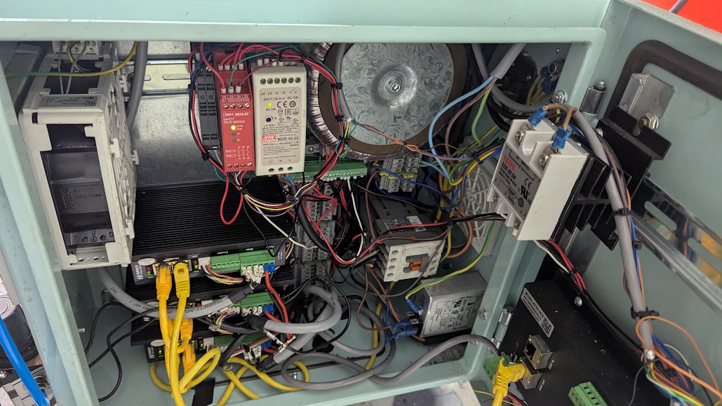
The power comes in at bottom right through an IEC connector with switch and EMI filter built in. We can't use this for your router as I wanted to keep it out of the filtered power.
Above that is the filtered power and above that are some Ocean Controls DIN tail terminals with the green earth one in the middle.
Above that is the round 60v AC toroids power supply for the stepper motors
Beside that is the 24 volt field power supply, red estop safety relay and a couple of slimline relays
At the right is a enclosure fan.
Below the 24v power supply is a tiny Mesa commx2 bus bar for field power. These are very cool.
and also a bunch of DIN rail terminals
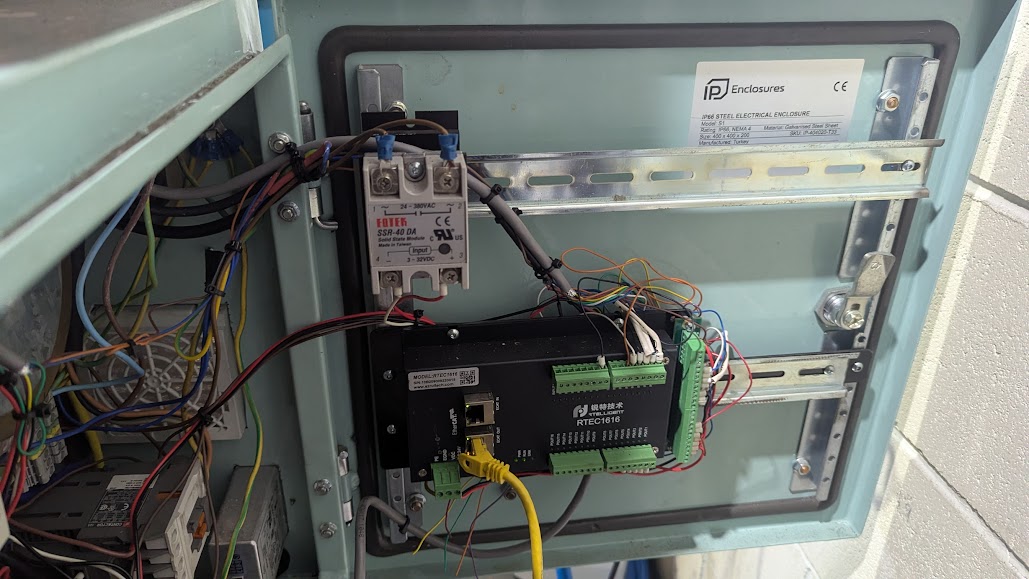
On the door is a SSR the same as I suggested for you mounted to a DIN rail heat sink
And a Ethercat 16 input and 16 outputs module
Good luck!
This is Ethercat so there is no Mesa card
I have also used a safety relay but that will add $400 or more so get the estop wired right to avoid it
The power comes in at bottom right through an IEC connector with switch and EMI filter built in. We can't use this for your router as I wanted to keep it out of the filtered power.
Above that is the filtered power and above that are some Ocean Controls DIN tail terminals with the green earth one in the middle.
Above that is the round 60v AC toroids power supply for the stepper motors
Beside that is the 24 volt field power supply, red estop safety relay and a couple of slimline relays
At the right is a enclosure fan.
Below the 24v power supply is a tiny Mesa commx2 bus bar for field power. These are very cool.
and also a bunch of DIN rail terminals
On the door is a SSR the same as I suggested for you mounted to a DIN rail heat sink
And a Ethercat 16 input and 16 outputs module
Good luck!
Attachments:
The following user(s) said Thank You: behai
Please Log in or Create an account to join the conversation.
- Hardware & Machines
- Computers and Hardware
- 4-Gang 1-Way Switch To Control 3 Power Supplies and a Router Independently
Time to create page: 0.170 seconds