- Hardware & Machines
- Computers and Hardware
- 4-Gang 1-Way Switch To Control 3 Power Supplies and a Router Independently
4-Gang 1-Way Switch To Control 3 Power Supplies and a Router Independently
- unknown
- Offline
- Platinum Member
-

Less
More
- Posts: 888
- Thank you received: 325
08 Apr 2025 15:02 #325939
by unknown
Replied by unknown on topic 4-Gang 1-Way Switch To Control 3 Power Supplies and a Router Independently
One thing you need to remember is that the PSU have an initial inrush current that is greater than the max current the PSU draws when running.
I went with fuses rather than circuit breakers.
I went with fuses rather than circuit breakers.
The following user(s) said Thank You: behai
Please Log in or Create an account to join the conversation.
- behai
- Offline
- Senior Member
-

Less
More
- Posts: 56
- Thank you received: 17
08 Apr 2025 15:49 #325941
by behai

The full PDF document address is: 100W Single Output Industrial DIN Rail Power Supply MDR-100 series
Best regards,
...behai.
Replied by behai on topic 4-Gang 1-Way Switch To Control 3 Power Supplies and a Router Independently
Thank you Rob. I have found the following specs on the MDR-100-24 PSU:One thing you need to remember is that the PSU have an initial inrush current that is greater than the max current the PSU draws when running.
I went with fuses rather than circuit breakers.
The full PDF document address is: 100W Single Output Industrial DIN Rail Power Supply MDR-100 series
Best regards,
...behai.
Please Log in or Create an account to join the conversation.
- tommylight
-

- Away
- Moderator
-

Less
More
- Posts: 21638
- Thank you received: 7393
08 Apr 2025 16:11 #325943
by tommylight
Replied by tommylight on topic 4-Gang 1-Way Switch To Control 3 Power Supplies and a Router Independently
We use these:
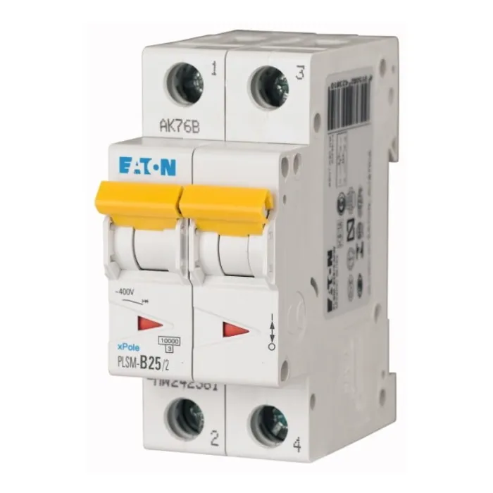
It's a fuse and a switch in the same box, the picture shows 2 of them.
It's a fuse and a switch in the same box, the picture shows 2 of them.
Attachments:
The following user(s) said Thank You: behai
Please Log in or Create an account to join the conversation.
- rodw
-

- Offline
- Platinum Member
-
Less
More
- Posts: 11960
- Thank you received: 4074
08 Apr 2025 19:14 #325953
by rodw
Replied by rodw on topic 4-Gang 1-Way Switch To Control 3 Power Supplies and a Router Independently
For a control box, the simplest way is to use a switched, EMI filtered and fused IEC connector
www.amazon.com.au/uxcell%C2%AE-IEC320-Sw...Filter/dp/B01FT0VRTS
You can see one of these used at the bottom right of my photo shared earlier.
But in your case, this won't work if you want to switch the router on and off because the current of the router will be too high for the typically 6 amp AC rating. Plus you would not want the electrically noisy router to be on the same side of the EMI filter as your electronics.
So in your case, I would use a fixed power lead and a cable gland to bring mains into the control box to two household breakers around 10 amp. One of these will protect your router circuit and the other your electronics, On the electronics circuit, immediately after the breaker, fit an EMI filter
www.jaycar.com.au/240v-ac-emi-filter/p/MS4001
Then connect all of your power supplies to the filtered mains power.
Filtering the power is really important to avoid spurious triggering from electrical noise. I learnt the hard way.
The next thing to work out is your estop. That's a bit tricky because you need to disable the router and the stepper motor power supply without using any relays that could fail. The estop needs to drop power to your router power and stepper mains motion. You could use 2 phases of a 3 phase breaker but technically you would then need to use a safety relay to be compliant.
Its probably acceptable to disable your stepper drivers using the enable pins on them that are usually left disconnected.
The following user(s) said Thank You: behai
Please Log in or Create an account to join the conversation.
- behai
- Offline
- Senior Member
-
Less
More
- Posts: 56
- Thank you received: 17
09 Apr 2025 07:43 #325967
by behai
I have been thinking about your advice on the router, I am trying something I don't have any practical knowledge of, I will just leave this one out, I will get the other three working, as my knowledge increase, I might rewire it again. This just my hobby project. But I really like learning electronics now, I have always been afraid of it.
You are right, the ENABLE pin on the CLT57T-V41 is left unconnected. During my learning of this driver, I used only the Raspberry Pi 4 and Python to program it, setting ENABLE to high disables the motor.
Best regards,
...behai.
Replied by behai on topic 4-Gang 1-Way Switch To Control 3 Power Supplies and a Router Independently
Thank you Rod,For a control box, the simplest way is to use a switched, EMI filtered and fused IEC connector
www.amazon.com.au/uxcell%C2%AE-IEC320-Sw...Filter/dp/B01FT0VRTS
You can see one of these used at the bottom right of my photo shared earlier.
But in your case, this won't work if you want to switch the router on and off because the current of the router will be too high for the typically 6 amp AC rating. Plus you would not want the electrically noisy router to be on the same side of the EMI filter as your electronics.
So in your case, I would use a fixed power lead and a cable gland to bring mains into the control box to two household breakers around 10 amp. One of these will protect your router circuit and the other your electronics, On the electronics circuit, immediately after the breaker, fit an EMI filter
www.jaycar.com.au/240v-ac-emi-filter/p/MS4001
Then connect all of your power supplies to the filtered mains power.
Filtering the power is really important to avoid spurious triggering from electrical noise. I learnt the hard way.
The next thing to work out is your estop. That's a bit tricky because you need to disable the router and the stepper motor power supply without using any relays that could fail. The estop needs to drop power to your router power and stepper mains motion. You could use 2 phases of a 3 phase breaker but technically you would then need to use a safety relay to be compliant.
Its probably acceptable to disable your stepper drivers using the enable pins on them that are usually left disconnected.
I have been thinking about your advice on the router, I am trying something I don't have any practical knowledge of, I will just leave this one out, I will get the other three working, as my knowledge increase, I might rewire it again. This just my hobby project. But I really like learning electronics now, I have always been afraid of it.
You are right, the ENABLE pin on the CLT57T-V41 is left unconnected. During my learning of this driver, I used only the Raspberry Pi 4 and Python to program it, setting ENABLE to high disables the motor.
Best regards,
...behai.
The following user(s) said Thank You: rodw
Please Log in or Create an account to join the conversation.
- behai
- Offline
- Senior Member
-
Less
More
- Posts: 56
- Thank you received: 17
09 Apr 2025 07:51 #325970
by behai
Thank you tommylight,
I understand now. When I searched for "automatic fuses", I did get correct result, such as this one www.aurinkopaneelikauppa.fi/Automatic-Fu...30V-AC-slow-Type-C-2; but I confused them for circuit breakers.
Best regards,
...behai.
Replied by behai on topic 4-Gang 1-Way Switch To Control 3 Power Supplies and a Router Independently
...
It's a fuse and a switch in the same box, the picture shows 2 of them.
Thank you tommylight,
I understand now. When I searched for "automatic fuses", I did get correct result, such as this one www.aurinkopaneelikauppa.fi/Automatic-Fu...30V-AC-slow-Type-C-2; but I confused them for circuit breakers.
Best regards,
...behai.
The following user(s) said Thank You: tommylight
Please Log in or Create an account to join the conversation.
- behai
- Offline
- Senior Member
-
Less
More
- Posts: 56
- Thank you received: 17
22 Jun 2025 13:32 #330689
by behai
Replied by behai on topic 4-Gang 1-Way Switch To Control 3 Power Supplies and a Router Independently
Good evening @tommylight, @unknown (Rob) and @rodw,
Thank you for your helps. I have been working on this. And I have something that is working.
I have since also purchased the MEAN WELL UHP-750-36 PSU au.mouser.com/ProductDetail/MEAN-WELL/UH...pnvY3grMpLJ29HELBwFs, and have it works with this setup, too.
Hi @rodw,
Follows your advice, I have bought the JayCar EMI Filter.
I bought six Earth terminals, while I need only three... The gentleman at the store was not able to to work out that the we don't need bus bar connector to join them, since the DIN rail acts as conductor since the Earth block clamps are metal:
Earth: www.altronics.com.au/p/p2415-dinkle-35a-...w-din-rail-terminal/
They also have DIN Rail fuse holder, too.
I have also last week received a 24VDC contactor from Tropac as you advised. It is a 3-phase one, as you have anticipated.
www.tropac.com.au/10-Pole-24VDC-Coil-5.5...Contactor-LS-Metasol
GMD-12M DC24V 5.5kW 3P Mini Contactor with 1NO Auxiliary Contact
And I have this flyback diode www.jaycar.com.au/diode-fr307-1000v-3a-d027-pack-10/p/ZR1052 to use with it.
I have since learned how to wire it, both switching a router (I used a Dremel grinder) and using the NO terminals to turn on an LED with a 9V battery when coil is turned on.
This is only with the contactor by itself. I have "worked out" how to wire it to the Mesa 7I96S -- but I don't know if it is correct yet.
(
In the process of learning the contactor, I have also learned that some single-phase power tool can't be switched via a contactor, such as this Milwaukee AGV 15-125-XE angle grinder: www.milwaukeetool.com.au/power-tools/met...ers/AGV15-125XE.html, because of start up protection, its manual states:
[
Startup protection:
When switched on, the machine will not start up after voltage breakdown. To continue working, switch the machine off and then on again.
]
So to be able to switch from the Mesa 7I96S, the wood router must not have this protection.
)
Thank you and best regards,
...behai.
Please Log in or Create an account to join the conversation.
- Hardware & Machines
- Computers and Hardware
- 4-Gang 1-Way Switch To Control 3 Power Supplies and a Router Independently
Time to create page: 0.184 seconds