- GCode and Part Programs
- G&M Codes
- Anyone with succesful Rack Type Tool Changer with Auto Tool length probe ?
Anyone with succesful Rack Type Tool Changer with Auto Tool length probe ?
- marq_torque
-
 Topic Author
- Offline
- Elite Member
-

Less
More
- Posts: 171
- Thank you received: 2
23 Apr 2019 19:16 #131679
by marq_torque
Anyone with succesful Rack Type Tool Changer with Auto Tool length probe ? was created by marq_torque
Hello everyone,
Trying to fix rack type Tool changer as shown in this thread,
forum.linuxcnc.org/38-general-linuxcnc-q...82-tool-change-setup
I want to execute tool touch program with each tool change, can some one send example ? i m noob with python and C+
I tried searching through forum but couldn't find. if i missed any existing post then requesting Admin to delete this thread.
Thanks in Advance.
Please Log in or Create an account to join the conversation.
- marq_torque
-
Topic Author
- Offline
- Elite Member
-
Less
More
- Posts: 171
- Thank you received: 2
23 Apr 2019 19:19 #131680
by marq_torque
Replied by marq_torque on topic Anyone with succesful Rack Type Tool Changer with Auto Tool length probe ?
I tried to do this back in time with Mach3 but its all mess, after M6 i used one additional M code macro to execute tool touch off,
I want to use only M6 T# to do this in rack type tool changer. if any help ?
I want to use only M6 T# to do this in rack type tool changer. if any help ?
Please Log in or Create an account to join the conversation.
- andypugh
-

- Offline
- Moderator
-

Less
More
- Posts: 19875
- Thank you received: 4642
23 Apr 2019 23:20 #131714
by andypugh
Replied by andypugh on topic Anyone with succesful Rack Type Tool Changer with Auto Tool length probe ?
There is a sample config for a rack-type changer
sim/axis/remap/rack-toolchange
Try running that to get a feel for it.
The "magic" is in the REMAP statement in the INI:
github.com/LinuxCNC/linuxcnc/blob/master...cktoolchange.ini#L58
Copy that to your config, then also copy the python and ncsubroutines folders to your own config
github.com/LinuxCNC/linuxcnc/blob/master...cktoolchange.ini#L58
(But they will also exist already in your installation, probably in /usr/share)
The tool change routine is handled in G-code:
github.com/LinuxCNC/linuxcnc/blob/master...ines/rack_change.ngc
That doesn't perform a length probe, but adding that is just a bit more G-code.
That said, if you have a rack changer, you shouldn't need a length probe.
The following user(s) said Thank You: marq_torque
Please Log in or Create an account to join the conversation.
- marq_torque
-
Topic Author
- Offline
- Elite Member
-
Less
More
- Posts: 171
- Thank you received: 2
24 Apr 2019 04:11 #131733
by marq_torque
Replied by marq_torque on topic Anyone with succesful Rack Type Tool Changer with Auto Tool length probe ?
Thanks AndyPugh,
I played with sample config, i am searching for io pinout for my parallel port breakout board. Just one output i need is tool clamp/declamp i m not able to find/understand hal output description
Also my rack is housing PCB drill type tools which spindle is picking tools directly by collet, and so tool holder is non existent. Any help would ve great where should i put my sample touch ptobe g code
I understand G38.xx commands n its working confused that where to add these lines so it goes to touch probe after tool change and return back to Z0 and move to previous XY co-ordinates.
Regards,
Ankit
Please Log in or Create an account to join the conversation.
- marq_torque
-
Topic Author
- Offline
- Elite Member
-
Less
More
- Posts: 171
- Thank you received: 2
24 Apr 2019 04:21 #131734
by marq_torque
Replied by marq_torque on topic Anyone with succesful Rack Type Tool Changer with Auto Tool length probe ?
Also one more thing, i m still noob to figure out how to set different pocket distance ? My pocket are slightly unequal distance say 0.05mm off, since my spindle is clamping tools directly its risk to break the tools while clamping.
Thanks,
Ankit
Thanks,
Ankit
Please Log in or Create an account to join the conversation.
- pl7i92
-

- Offline
- Platinum Member
-

Less
More
- Posts: 1872
- Thank you received: 358
24 Apr 2019 09:56 #131751
by pl7i92
Replied by pl7i92 on topic Anyone with succesful Rack Type Tool Changer with Auto Tool length probe ?
you probe the tool to the Rack toolchanger
so manuel load the tool then toolprobe
the length goes into the tooltable
MY Personal use is a ToolProbe Tool called T100
it is 100mm +- 0,01 of length and asigned to G59.3 THE LAST Coordinate system available
the G59.3 is at the Renishaw Zero with that tool
so i MDI
G55
T100 M6
G43 H100 (this is Zero )
G30 Move too tool probe Pos XY
G38.2 G91 Z-100 F40
G90
HERE we SEE if we are still ZERO
Manuell move up
Change tool in to be mesurerd
G38.2 G91 Z-100 F40
now you see a number Z in DRO
this is the Tool ofset to be enterd inside tooltable of the Tool you are storing the Rack-TC
so saying you store T4
G10 L11 P4 Zx (where Zx is the DRO or you can do it with the Value of the Zcordinate Parameter #54xx
THIS VAN BE BUTTON AUTOMATED
Tool probe.ngc
5221-5230 - Coordinate System 1, G54 for X, Y, Z, A, B, C, U, V, W & R. R denotes the XY rotation angle around the Z axis. Persistent.
5241-5250 - Coordinate System 2, G55 for X, Y, Z, A, B, C, U, V, W & R. Persistent.
5261-5270 - Coordinate System 3, G56 for X, Y, Z, A, B, C, U, V, W & R. Persistent.
5281-5290 - Coordinate System 4, G57 for X, Y, Z, A, B, C, U, V, W & R. Persistent.
5301-5310 - Coordinate System 5, G58 for X, Y, Z, A, B, C, U, V, W & R. Persistent.
5321-5330 - Coordinate System 6, G59 for X, Y, Z, A, B, C, U, V, W & R. Persistent.
5341-5350 - Coordinate System 7, G59.1 for X, Y, Z, A, B, C, U, V, W & R. Persistent.
5361-5370 - Coordinate System 8, G59.2 for X, Y, Z, A, B, C, U, V, W & R. Persistent.
5381-5390 - Coordinate System 9, G59.3 for X, Y, Z, A, B, C, U, V, W & R. Persistent.
The following user(s) said Thank You: marq_torque
Please Log in or Create an account to join the conversation.
- marq_torque
-
Topic Author
- Offline
- Elite Member
-
Less
More
- Posts: 171
- Thank you received: 2
24 Apr 2019 10:12 #131756
by marq_torque
Replied by marq_torque on topic Anyone with succesful Rack Type Tool Changer with Auto Tool length probe ?
Thanks for guidance,
If i am not wrong you suggesting me additional code for touch probe after tool change? If it is then i tried same method back time in mach 3 i issed M6T# and later M177 for tool touch. and at this time i am not able to get customised M code output in my cam system and also need it little simple so wanted to clup this touch probe routine in M6T# code. If any help ??
Regards,
Ankit
Please Log in or Create an account to join the conversation.
- andypugh
-
- Offline
- Moderator
-
Less
More
- Posts: 19875
- Thank you received: 4642
24 Apr 2019 14:46 #131770
by andypugh
Replied by andypugh on topic Anyone with succesful Rack Type Tool Changer with Auto Tool length probe ?
The sample config is set up so that M6 calls a G-code subroutine.
(rack_change.ngc, linked to above)
You would modify that routine to also do a tool length probe, and to set the new calculated length in the tool table with an G10 command.
linuxcnc.org/docs/2.7/html/gcode/g-code.html#gcode:g10-l1
Note the different functions of G10 L1, G10 L2, G10 L10 and G10 L11.
I think that you would just make a probe move to the touch-plate then issue a G10 L10 Znn where nn is the known position of the touch plate (possibly in an otherwise unused coordinate system).
To allow for different slot locations, I think I would use the U,V colums of the tool table as the tool location.
The following user(s) said Thank You: marq_torque
Please Log in or Create an account to join the conversation.
- marq_torque
-
Topic Author
- Offline
- Elite Member
-
Less
More
- Posts: 171
- Thank you received: 2
24 Apr 2019 16:16 #131773
by marq_torque
Replied by marq_torque on topic Anyone with succesful Rack Type Tool Changer with Auto Tool length probe ?
Hello AndyPugh,
Thanks for responding, yes i m understanding what you suggested.
1) Can you explain how to activate Pneumatic cylinder using parallel port configuration to declamp tool how to setup output pin delay and all ? I m not able to find any details of output.
2) Also in last lines you said that tool table decides tool pocket Location, if i am using that tool table so what lines to remove in INI ? Or am i understanding wrong ?
Regards,
Ankit
Please Log in or Create an account to join the conversation.
- marq_torque
-
Topic Author
- Offline
- Elite Member
-
Less
More
- Posts: 171
- Thank you received: 2
24 Apr 2019 16:26 #131774
by marq_torque
Replied by marq_torque on topic Anyone with succesful Rack Type Tool Changer with Auto Tool length probe ?
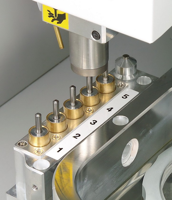
This is tool rack for my machine, last one is tool touch probe. These pockets have inaccurate repeatability length wise.
So cant save tools for entire day jobs. And i want this to be idiot proof so not adding extra codes in part program manually.
Thanks,
Ankit
So cant save tools for entire day jobs. And i want this to be idiot proof so not adding extra codes in part program manually.
Thanks,
Ankit
Please Log in or Create an account to join the conversation.
- GCode and Part Programs
- G&M Codes
- Anyone with succesful Rack Type Tool Changer with Auto Tool length probe ?
Time to create page: 0.123 seconds