Beginner trying to learn basic programming
- usert_l
- Offline
- Junior Member
-

Less
More
- Posts: 27
- Thank you received: 2
29 May 2019 03:44 #135242
by usert_l
Beginner trying to learn basic programming was created by usert_l
Hi,
So I'm not sure if this is the right place to ask but I'm trying to learn some basic hand programming on my own specifically for cnc lathe. I've read as much as I can about some common g codes and what they mean as well as learning about the X and Z coordinates.
As an exercise I want to develop a program for the simple part in my sketch, but really just don't really know how to start. It has a taper and a ball shape at the end. Can someone show me an example program that show what's involved?
Another thing I don't know is what software to use to practice hand writing program in and use later to test run on a lathe. Can I type in something like Microsoft Notepad and save as text document?
Please Log in or Create an account to join the conversation.
- pl7i92
-

- Offline
- Platinum Member
-

Less
More
- Posts: 1872
- Thank you received: 358
29 May 2019 06:17 #135248
by pl7i92
Replied by pl7i92 on topic Beginner trying to learn basic programming
in linuxcnc is mainly gedit as the edior has nice coloring g-code
you can make a start here
Video showes Full Hand G-coding of a CRC tool path
you can make a start here
Video showes Full Hand G-coding of a CRC tool path
The following user(s) said Thank You: usert_l
Please Log in or Create an account to join the conversation.
- andypugh
-

- Offline
- Moderator
-

Less
More
- Posts: 19876
- Thank you received: 4642
29 May 2019 14:11 - 29 May 2019 14:11 #135270
by andypugh
Replied by andypugh on topic Beginner trying to learn basic programming
You need to break the shape down in to arcs and lines and also work out where you want the roughing passes to go.
I would suggest first either making an accurate scale drawing on paper or using CAD of both the required shape and the starting stock.
You can then draw note the critical points where arcs and lines intersect, and draw in your roughing passes as horizontal lines.
Doing this will also allow you to determine what tool geometry you need to make the part. (40 degree back angle, according to the drawing I just made in CAD).
You will find it easier to work in radius mode when hand coding arcs on a lathe. And you need to be in the XZ plane. You might prefer to use absolute arc-centre mode too.Then spindle speed and feed rate. I like CSS and feed-per revAll your G-code programs will start like this.
I suggest keeping this page to-hand:
linuxcnc.org/docs/2.7/html/gcode.html
Decide where your coordinate origin is. I like to use the -ve end of the material as zero, and that makes all y Z numbers negative.
Then measure the start and end positions of your roughing passes on your drawing, stopping slightly short of the profile. These form a sequence of rapid to start / feed move to end, feed out (or rapid out, rapid Z retract / Rapid X return / feed in moves.
Then program the finishing pass. If the sphere needs to be truly spherical then you need to compensate for nose-radius (G40 / G41) but initially it is easier not to.
Deciding where the arc finishes can be a little difficult if scaling from a hand drawing but you have chosen a convenient place for the arc end.
Note that lathe arc direction (clockwise / anticlockwise is as if you are lying on the floor looking up with a conventional front-toolpost lathe and as if looking down on a back toolpost
Then a retract to a safe place(G0 Xnn Znn) , spindle off (M5), coolant off (M9), end programme (M2)
This becomes much easier with G71 / G72 lathe macros, then you only need to programme the finish profile. There are ways to add that, and work is under way to do it as a built-in code.
Hand coding can let you do things that CAM never could. specially if you like maths and geometry:
bodgesoc.blogspot.com/2016/11/cams.html
I would suggest first either making an accurate scale drawing on paper or using CAD of both the required shape and the starting stock.
You can then draw note the critical points where arcs and lines intersect, and draw in your roughing passes as horizontal lines.
Doing this will also allow you to determine what tool geometry you need to make the part. (40 degree back angle, according to the drawing I just made in CAD).
You will find it easier to work in radius mode when hand coding arcs on a lathe. And you need to be in the XZ plane. You might prefer to use absolute arc-centre mode too.
G8 G90.1 G20 G18G95 F0.006 ; 6 thou per rev
G96 S200 ; 200 ft/min
M8 ; coolant on
M3 ; start the spindleI suggest keeping this page to-hand:
linuxcnc.org/docs/2.7/html/gcode.html
Decide where your coordinate origin is. I like to use the -ve end of the material as zero, and that makes all y Z numbers negative.
Then measure the start and end positions of your roughing passes on your drawing, stopping slightly short of the profile. These form a sequence of rapid to start / feed move to end, feed out (or rapid out, rapid Z retract / Rapid X return / feed in moves.
Then program the finishing pass. If the sphere needs to be truly spherical then you need to compensate for nose-radius (G40 / G41) but initially it is easier not to.
Deciding where the arc finishes can be a little difficult if scaling from a hand drawing but you have chosen a convenient place for the arc end.
Note that lathe arc direction (clockwise / anticlockwise is as if you are lying on the floor looking up with a conventional front-toolpost lathe and as if looking down on a back toolpost
G0 Z0.02
G0 X0
G1 Z0
G3 X0.3 Z-0.6 I0 K-0.3
G1 X0.3 Z-0.8
G1 X0.5 Z-1.8
Then a retract to a safe place(G0 Xnn Znn) , spindle off (M5), coolant off (M9), end programme (M2)
This becomes much easier with G71 / G72 lathe macros, then you only need to programme the finish profile. There are ways to add that, and work is under way to do it as a built-in code.
Hand coding can let you do things that CAM never could. specially if you like maths and geometry:
bodgesoc.blogspot.com/2016/11/cams.html
Last edit: 29 May 2019 14:11 by andypugh.
The following user(s) said Thank You: usert_l
Please Log in or Create an account to join the conversation.
- BigJohnT
-

- Offline
- Administrator
-

Less
More
- Posts: 3990
- Thank you received: 994
30 May 2019 12:08 - 30 May 2019 12:09 #135380
by BigJohnT
Replied by BigJohnT on topic Beginner trying to learn basic programming
My Arc Generator may help you sort out the arc portions of your G code.
github.com/LinuxCNC/simple-gcode-generators/tree/master/arcgen
My lathe subroutines may also help... I use these for 90% of my lathe ops.
gnipsel.com/files/chnc/subroutines/
JT
github.com/LinuxCNC/simple-gcode-generators/tree/master/arcgen
My lathe subroutines may also help... I use these for 90% of my lathe ops.
gnipsel.com/files/chnc/subroutines/
JT
Last edit: 30 May 2019 12:09 by BigJohnT.
The following user(s) said Thank You: usert_l, Dinuka_Shehan
Please Log in or Create an account to join the conversation.
- usert_l
- Offline
- Junior Member
-
Less
More
- Posts: 27
- Thank you received: 2
30 May 2019 17:10 #135406
by usert_l
Replied by usert_l on topic Beginner trying to learn basic programming
Thanks Andy for your suggestion. I sat down and made a scale drawing of the part I want to learn to program the cutting. The lathe I will be learning on is metric, not inches. So I changed dimensions on my scale drawing for the part to be in mm. The part is also smaller too because I will later practice making it from small 1/4" aluminum stock. The overall shape of the part is still the same as that in my original hand sketch.
I hand wrote the program below for the part. It has three main cuts. The first is the linear roughing pass that cuts out a small corner of the stock. The second is a roughing pass that follows the profile of the part but leaves about 0.10mm material thickness left for the finishing pass. And the last cut is the finishing cut (0.10mm depth of cut).
The second and last cut is a combination of linear and arc moves that I learned. All the X and Z coordinates I noted on the drawing are my best estimate based on the grid scale paper I made the drawing on (attached). I drew a cutting tool to show where it's located relative to the aluminum stock. The lathe has a cross slide and the tool is mounted on a quick change tool post. The tool will cut in front of stock (tool close to the operator).
As far as tooling goes, I like 55 deg carbide insert tool. For a profile shape like this, should I use it in a straight insert tool holder? In manual operations I only use LH or RH tool holders. But I'm afraid that a 55 deg insert in RH holder has about a 30 deg back angle, which probably isn't enough for proper geometry near the end of the arc cut. A straight insert holder will allow enough back angle for tight corners, but I don't have any experience yet with it.
The program codes I worked on:
G8 G90.1 G21 G18
G95 F0.10 ; 0.10 mm per rev
G96 S91 ; 91 meter per minute converted from 300 SFPM for aluminum
M3
G0 Z1
G0 X-2.3
G1 Z-0.6
G0 X-4 Z1.1
G0 Z4
G0 X-1.4
G1 Z0
G3 X-2.6 Z-4.3 I0 K-2.75
G1 X-2.6 Z-5.3
G1 X-3.175 Z10
G0 X-5
G0 Z4
G1 X-1.2
G1 Z0
G3 X-2.5 Z-4.25 I0 K-2.75
G1 Z-5.25
G1 X-3.175 Z-11.4
G0 X-4
G0 Z4
M5
M2
Please Log in or Create an account to join the conversation.
- andypugh
-
- Offline
- Moderator
-
Less
More
- Posts: 19876
- Thank you received: 4642
30 May 2019 17:38 #135410
by andypugh
I changed a few things, and got this.
I suggest you try the same thing, ie try running your code on the sim/axis/lathe simulator config to see your toolpaths.
I changed the negative X coordinates to be positive. (I don't think it matters with a lathe, but it seems an odd thing to do)
I changed the arcs to R format, because solving IK format from a hand drawing is difficult.
I changed the Z in G1 X-3.175 Z10 because that went straight through the ball....
Replied by andypugh on topic Beginner trying to learn basic programming
I wish you had said, I assumed inches from the drawing. I actually had to convert everything from metric to imperial, as I use metric pretty much exclusively.The lathe I will be learning on is metric, not inches.
G8 G90.1 G21 G18
G95 F0.10 ; 0.10 mm per rev
G96 S91 ; 91 meter per minute converted from 300 SFPM for aluminum
M3
G0 Z1
G0 X-2.3
G1 Z-0.6
G0 X-4 Z1.1
G0 Z4
G0 X-1.4
G1 Z0
G3 X-2.6 Z-4.3 I0 K-2.75
G1 X-2.6 Z-5.3
G1 X-3.175 Z10
G0 X-5
G0 Z4
G1 X-1.2
G1 Z0
G3 X-2.5 Z-4.25 I0 K-2.75
G1 Z-5.25
G1 X-3.175 Z-11.4
G0 X-4
G0 Z4
M5
M2
I changed a few things, and got this.
I suggest you try the same thing, ie try running your code on the sim/axis/lathe simulator config to see your toolpaths.
I changed the negative X coordinates to be positive. (I don't think it matters with a lathe, but it seems an odd thing to do)
I changed the arcs to R format, because solving IK format from a hand drawing is difficult.
I changed the Z in G1 X-3.175 Z10 because that went straight through the ball....
The following user(s) said Thank You: usert_l
Please Log in or Create an account to join the conversation.
- usert_l
- Offline
- Junior Member
-
Less
More
- Posts: 27
- Thank you received: 2
02 Jun 2019 21:56 - 02 Jun 2019 21:58 #135660
by usert_l
Replied by usert_l on topic Beginner trying to learn basic programming
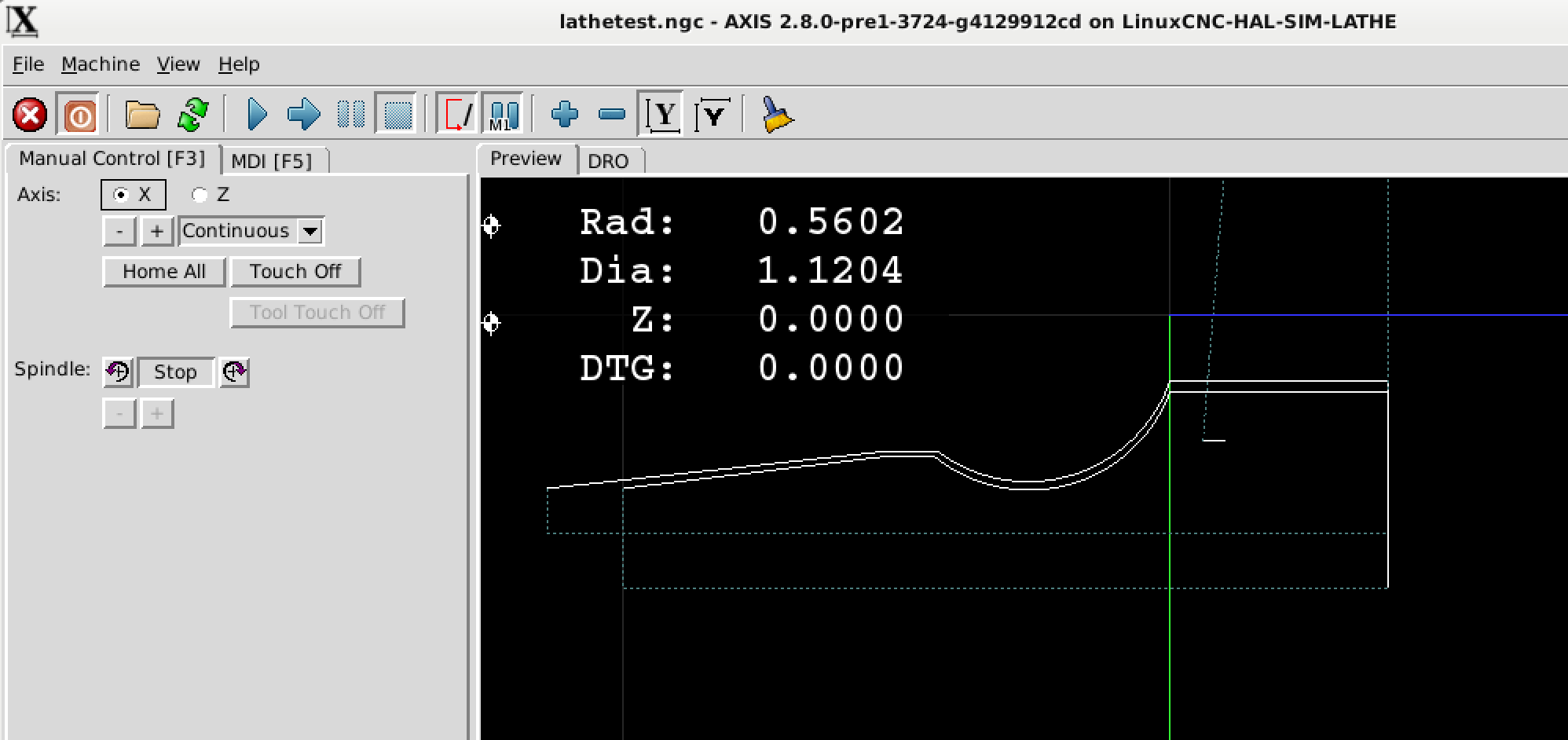
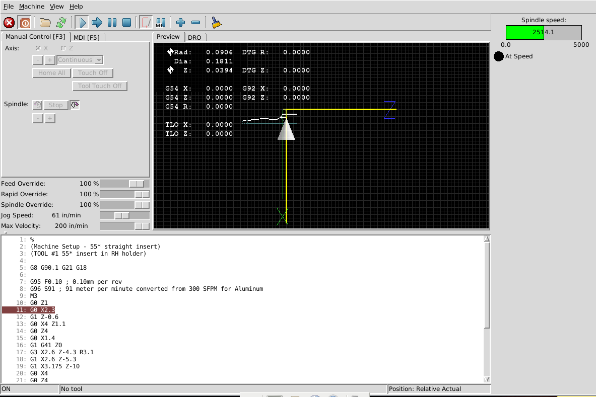
I made and saved the changes as suggested, and then open up the program in the sim/axis/lathe simulator config.
Before I can click run, I had to click home all axes (that when it moves and creates those two yellow lines parallel to the X and Z axes).
I then click run and for some reason it keeps stopping at line 11 ... I don't know what's causing that. This is first time I'm in the lathe simulator.
Before I can click run, I had to click home all axes (that when it moves and creates those two yellow lines parallel to the X and Z axes).
I then click run and for some reason it keeps stopping at line 11 ... I don't know what's causing that. This is first time I'm in the lathe simulator.
Attachments:
Last edit: 02 Jun 2019 21:58 by usert_l.
Please Log in or Create an account to join the conversation.
- andypugh
-
- Offline
- Moderator
-
Less
More
- Posts: 19876
- Thank you received: 4642
02 Jun 2019 23:02 #135671
by andypugh
Replied by andypugh on topic Beginner trying to learn basic programming
I think it is actually waiting for spindle-at-speed.
Though why the sim would fail to reach speed is a mystery to me.
Try adding D5000 to the G96 line
Though why the sim would fail to reach speed is a mystery to me.
Try adding D5000 to the G96 line
The following user(s) said Thank You: usert_l
Please Log in or Create an account to join the conversation.
- usert_l
- Offline
- Junior Member
-
Less
More
- Posts: 27
- Thank you received: 2
03 Jun 2019 04:01 #135690
by usert_l
Replied by usert_l on topic Beginner trying to learn basic programming
Ok it seems to be working now. Spindle max speed limit seems to be about 2500. If I set anything higher than that, the spindle would never be able to reach that speed. So I had to make it D2500 instead to the G96 line.
I do have a question about the G96 constant surface speed mode ... I believe that it automatically adjusts the spindle speed according to how close or far away the cutting tool position is relative to the centerline of the stock (Z axis), as the tool cuts along the profile of the part. However, I noticed that the spindle RPM pretty much stays constant @ 2500 throughout the entire program in the simulator config. Is that something that the simulator config doesn't take into account?
I do have a question about the G96 constant surface speed mode ... I believe that it automatically adjusts the spindle speed according to how close or far away the cutting tool position is relative to the centerline of the stock (Z axis), as the tool cuts along the profile of the part. However, I noticed that the spindle RPM pretty much stays constant @ 2500 throughout the entire program in the simulator config. Is that something that the simulator config doesn't take into account?
Please Log in or Create an account to join the conversation.
- andypugh
-
- Offline
- Moderator
-
Less
More
- Posts: 19876
- Thank you received: 4642
03 Jun 2019 04:32 #135691
by andypugh
Replied by andypugh on topic Beginner trying to learn basic programming
It looks like the sim config tops out at 2500, so that is pretty much what you will see with small diameter work and a high surface speed.
You can edit the config, though bear in mind that this limit might not exist in the HAL of a real machine.
Have a look in the HAL at the "limit_speed" pins and parameters.
(And note that, because of what it is, maxv = acceleration, and max = max velocity)
You can edit the config, though bear in mind that this limit might not exist in the HAL of a real machine.
Have a look in the HAL at the "limit_speed" pins and parameters.
(And note that, because of what it is, maxv = acceleration, and max = max velocity)
Please Log in or Create an account to join the conversation.
Time to create page: 0.202 seconds