hy_VFD hy_VFD vfd.speed-command not setting RPM
- sir_wolf_art
-
 Topic Author
- Offline
- New Member
-

- Posts: 9
- Thank you received: 0
I have communication to the VFD somewhat but I am running into some issues. I have used Tutorials from Marco Reps on youtube and have set my VFD the same way as he did.
I've been testing in halrun to make sure I have mostly everything working properly and I'm finding I can turn on a spindle and set Direction but I cannot set RPM even know when I do show pin it is listening to correct RPM sets but the vfd does not change RPM accordingly it seems like it's going to full RPM each time the following is the information that I getting back from halrun.
#halcmd: loadusr -Wn vfd hy_vfd -n vfd -d /dev/ttyUSB0 -p none -r 9600 -s 1
#halcmd: setp vfd.enable 1
#halcmd: setp vfd.speed-command 600
#halcmd: setp vfd.spindle-forward 1
#halcmd: show pin
Component Pins:
Owner Type Dir Value Name
5 float OUT 270 vfd.ACV
5 float OUT 9 vfd.CNST
5 bit OUT FALSE vfd.CNST-bracking
5 bit OUT FALSE vfd.CNST-command-rf
5 bit OUT FALSE vfd.CNST-jog
5 bit OUT FALSE vfd.CNST-jogging
5 bit OUT TRUE vfd.CNST-run
5 bit OUT TRUE vfd.CNST-running
5 bit OUT FALSE vfd.CNST-running-rf
5 bit OUT FALSE vfd.CNST-track-start
5 float OUT 1 vfd.CNTR
5 float OUT 0 vfd.Cont
5 float OUT 1627 vfd.DCV
5 float OUT 4.5 vfd.OutA
5 float OUT 49.5 vfd.OutF
5 float OUT 3042 vfd.Rott
5 float OUT 100 vfd.SetF
5 float OUT 0 vfd.Tmp
5 float OUT 400 vfd.base-freq
5 bit IN TRUE vfd.enable
5 float OUT 100 vfd.freq-lower-limit
5 float OUT 10000 vfd.frequency-command
5 bit OUT TRUE vfd.hycomm-ok
5 float OUT 400 vfd.max-freq
5 u32 OUT 0x00000002 vfd.motor-poles
5 float OUT 7 vfd.rated-motor-current
5 float OUT 24000 vfd.rated-motor-rev
5 float OUT 120 vfd.rated-motor-voltage
5 float IN 600 vfd.speed-command
5 bit OUT FALSE vfd.spindle-at-speed
5 float IN 0.02 vfd.spindle-at-speed-tolerance
5 bit IN TRUE vfd.spindle-forward
5 bit IN TRUE vfd.spindle-on
5 bit IN FALSE vfd.spindle-reverse
5 float OUT 2970 vfd.spindle-speed-fb
VFD side settings
PD001 = 2
PD002 = 2
PD163 = 1
PD164 = 1
PD165 = 3
Other References used
forum.linuxcnc.org/24-hal-components/325...ang-vfd-using-runhal
linuxcnc.org/docs/html/man/man1/hy_vfd.1.html
Please Log in or Create an account to join the conversation.
- andypugh
-

- Offline
- Moderator
-

- Posts: 19861
- Thank you received: 4636
Please Log in or Create an account to join the conversation.
- sir_wolf_art
-
Topic Author
- Offline
- New Member
-
- Posts: 9
- Thank you received: 0
Please Log in or Create an account to join the conversation.
- andypugh
-
- Offline
- Moderator
-
- Posts: 19861
- Thank you received: 4636
I was referring to PD002 = 2 which you already have.
linuxcnc.org/docs/2.7/html/man/man1/hy_vfd.1.html
Says to set PD164 to 2, you have 1.
Maybe your minimum motor frequency is set quite high?
Please Log in or Create an account to join the conversation.
- curtisa
- Offline
- Premium Member
-

- Posts: 88
- Thank you received: 15
5 float OUT 100 vfd.freq-lower-limit
It looks like you have PD011 set to 100Hz. If you send a speed command of 600 to the VFD you're asking it to run the spindle at 600RPM = 10Hz. The Huanyang VFDs will not respond to a spindle speed command until send it a value higher than PD011. You'll probably find that if you send a speed command greater than 6000 you'll see the VFD spin up to the correct speed.
Please Log in or Create an account to join the conversation.
- sir_wolf_art
-
Topic Author
- Offline
- New Member
-
- Posts: 9
- Thank you received: 0
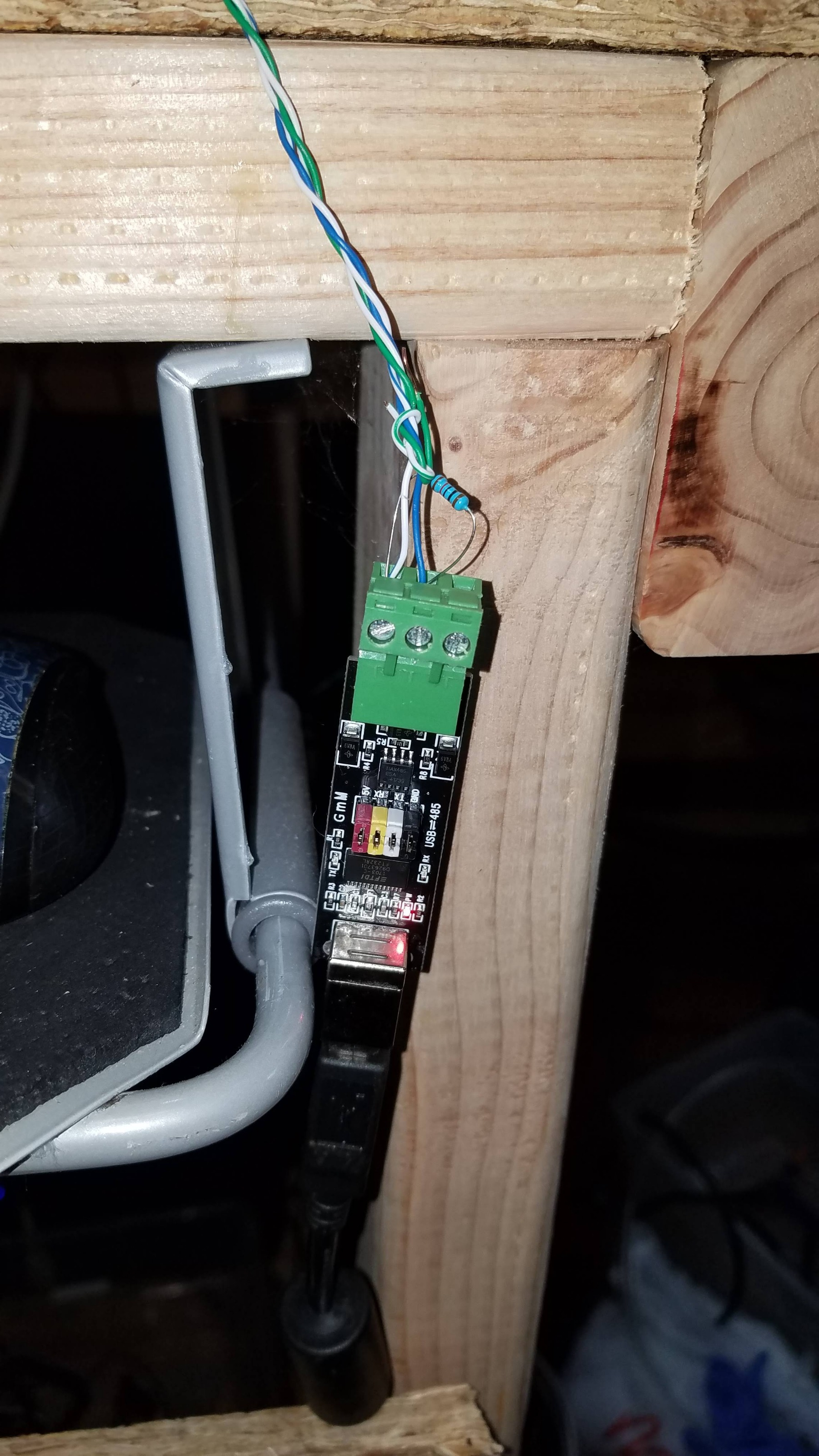
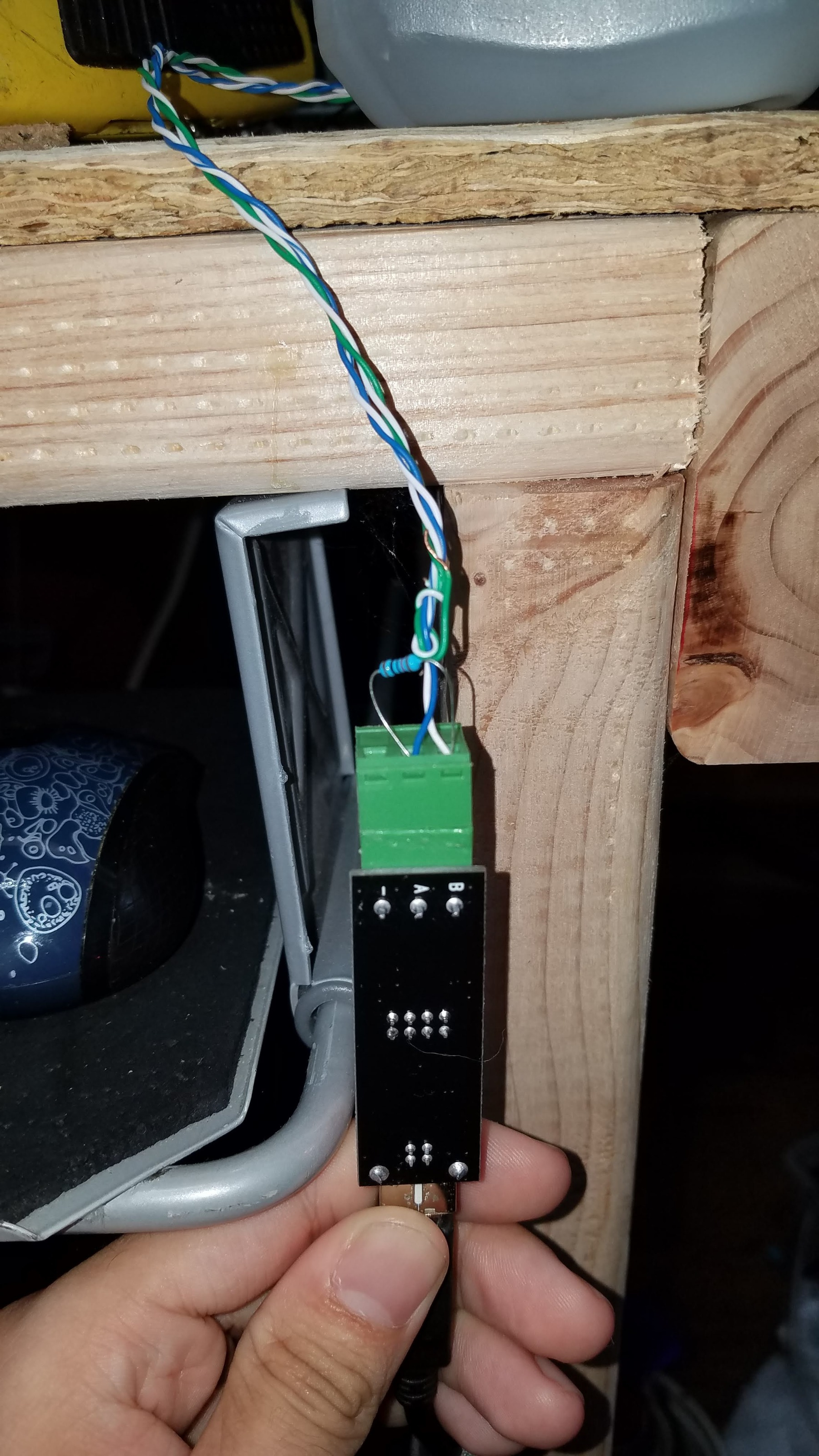
I going to incould pics of the wiring as am also using 2 120ohm resistor on both ends of the twisted pair cable on I'm using.
I know i should Shielding on the twisted pair cable and vfd cable I haven't had the money to buy the VFD cable yet. I am using the wire that came with the machine originally.
This is the machine that i am converting to work with Linuxcnc. www.automationtechnologiesinc.com/produc.../cnc-router/hy-3040/
I am getting the following when in halcmd none stop after starting the spindle.
ERROR Communication time out (-12)
WAIT_DATA(): comms time out
What does work right now is commands going to the VFD. i can set RPM now YAY!
I'm also have you ever questions on this component if you guys don't mind and I'm still learning all this.
Curtisa sayed “600 RPM = 10hz” How does one calculate RPM from HZ is there a formula for this?
The man page for this component ( linuxcnc.org/docs/html/man/man1/hy_vfd.1.html ) Under the pin Section of the page Pins “
Please Log in or Create an account to join the conversation.
- curtisa
- Offline
- Premium Member
-
- Posts: 88
- Thank you received: 15
I am getting the following when in halcmd none stop after starting the spindle.
ERROR Communication time out (-12)
WAIT_DATA(): comms time out
What does work right now is commands going to the VFD. i can set RPM now YAY!
If you're getting 'Communication time out (-12)' errors but still able to control the VFD then the comms between the computer and VFD must be dropping in and out occasionally. Maybe there is a difference in communications parameters between the two (eg, stop bits). Can you confirm that the 'loadusr' command you are using is still:
loadusr -Wn vfd hy_vfd -n vfd -d /dev/ttyUSB0 -p none -r 9600 -s 1And that the VFD is still set as:
PD001 = 2
PD002 = 2
PD163 = 1
PD164 = 1
PD165 = 3
Maybe the USB-to-RS485 converter is faulty? They are pretty cheap, so you could order a new one to try swapping out.
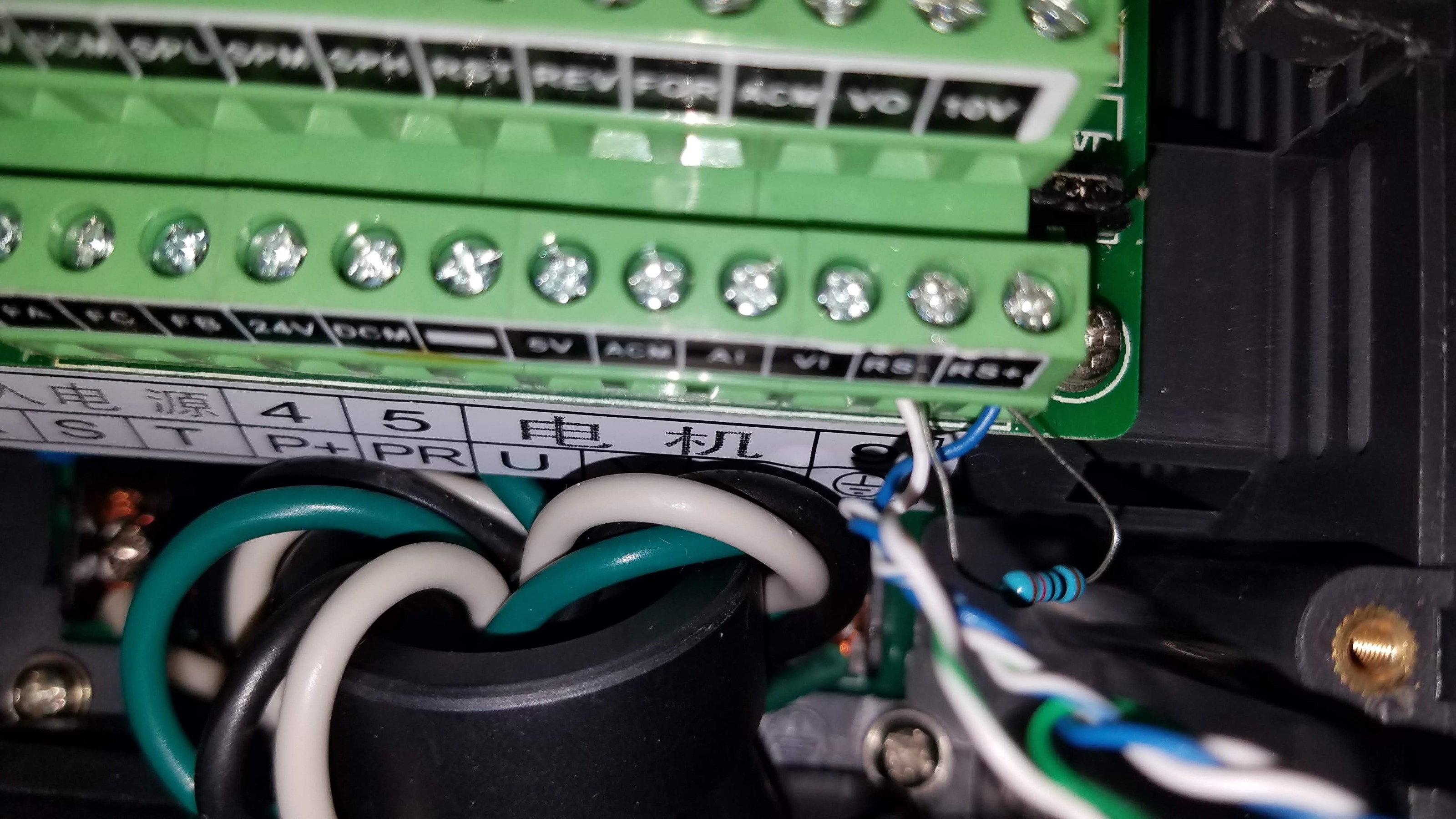
Shielded RS485 cable will help, particularly since you seem to have your RS485 data wires positioned quite close to the motor wires in that bottom photo.
Terminating 120ohm resistors may not be required. The assumption is neither your USB-to-RS485 converter or the VFD have them installed internally, which may or may not be the case. FWIW I have not installed terminating resistors on my HY setup and comms works fine with no errors.
How does one calculate RPM from HZ is there a formula for this?
Your max RPM is 24000 and max frequency is 400Hz. Therefore your ratio of RPM to frequency is 24000/400 = 60 RPM per Hz. So sending a command of 600 RPM to the VFD = (600 RPM) / (60 RPM per Hz) = 10Hz.
The man page for this component ( linuxcnc.org/docs/html/man/man1/hy_vfd.1.html ) Under the pin Section of the page Pins “
.SetF” “ .OutF” “ .OutA” “ .Rott” “ .DCV” “ .ACV” “ .Cont” “ .Tmp” I have guess what some of these pins are out putting but others no idea. It would nice to see the man page to update to show what these pins are for.
Work is underway to update the info in a lot of the manual pages.
Please Log in or Create an account to join the conversation.
- andypugh
-
- Offline
- Moderator
-
- Posts: 19861
- Thank you received: 4636
For Modbus I like to use DMX cable (as a handy 2-core+ screen)
www.ebay.co.uk/itm/131434045475
I can't decide whether this would be useful for a VFD, or a terrible noise problem waiting to happen:
www.ebay.co.uk/itm/162856829053
Please Log in or Create an account to join the conversation.
- sir_wolf_art
-
Topic Author
- Offline
- New Member
-
- Posts: 9
- Thank you received: 0
yea some thing was not right with it. Luckily I had a spare on hand that i was using for programming with an Arduino (try learn modbus). It is communicating properly now.Maybe the USB-to-RS485 converter is faulty? They are pretty cheap, so you could order a new one to try swapping out.
Only thing I got left figure out on the spindle is to figure out which one of the this pins is the voltage output feedback form the VFD so I can Calculate Wattage.
I know vfd.OutA is amps out but what about Volts out? It has to be vfd.DCV or vfd.ACV but i cant figure out which one's the right one they both seem off somehow compare to my old vfd was telling me.“<name>.SetF” “<name>.OutF” “<name>.OutA” “<name>.Rott” “<name>.DCV” “<name>.ACV” “<name>.Cont” “<name>.Tmp”
Not a bad idea done setup. Could also use DMX premade cables with the connectors to match.For Modbus I like to use DMX cable (as a handy 2-core+ screen)
www.ebay.co.uk/itm/131434045475
Both I think… if the main power cable was Shielded then yea it could work as a power in to the vfd from the Main control cabinet. Which in itself would make it look neat wiring wise. I'm still trying to decide if I still want to get a vfd cable for the main spindle $40 quite a bit for a cable for me when i can only fork over $200 a month.I can't decide whether this would be useful for a VFD, or a terrible noise problem waiting to happen: www.ebay.co.uk/itm/162856829053
But thank you both for your guy's help on this. I Still have a lot to do on this CNC mill so more Questions well come. I'm hoping by the end of the project I can put together a good guide for people to showed them how to convert to Linuxcnc. Thank you again!!! For me on to probe and limit Switches denouncing.
Please Log in or Create an account to join the conversation.
- curtisa
- Offline
- Premium Member
-
- Posts: 88
- Thank you received: 15
I know vfd.OutA is amps out but what about Volts out? It has to be vfd.DCV or vfd.ACV but i cant figure out which one's the right one they both seem off somehow compare to my old vfd was telling me.
.DCV is the DC bus voltage inside the VFD that it is using to generate the PWM AC voltage to apply to the motor. .ACV is the AC voltage being applied to the motor while it is running, which will be dependent on how you have the VFD programmed to match the motor volts-per-hertz characteristics.
If you issue a 'show pin' command with the VFD stationary and again when it is running you'll notice the .DCV value sits at a fairly constant value. .ACV will be 0 when the VFD is stopped and some other value that increases with speed when running.
Not a bad idea done setup. Could also use DMX premade cables with the connectors to match.
Or even some generic two-core shielded microphone cable. RS485 is, by design a fairly robust protocol, so you don't need to spend a fortune on premium shielded cables to get reliable performance.
Please Log in or Create an account to join the conversation.