7i76e spindle analog issues
- simonmn
- Offline
- Senior Member
-

Less
More
- Posts: 40
- Thank you received: 4
21 Apr 2019 09:03 #131377
by simonmn
7i76e spindle analog issues was created by simonmn
Still working on my Mazak lathe, but have since upgraded to a 7i76e. I got almost everything working, but are getting stuck at the spindle... again.
I used to control the spindle with a Chinese break out board hooked up to a DAC sending my 0-10v to the spindle.
Now with the 7i76e, spindle- is connected to TB4 pin 1, a down converted 10v is connected to pin 3, while spindle + is unconnected but is to be on pin 2.
Cant really get pin 2 to do anything. If I measure from pin 1 and 2 I get a solid 0.45mV, regardless of commands S500 M3 or S6000 M3(Max rpm)
I am getting a little worried that I might have fried the board, or the spindle control part, but otherwise fully expecting my issue to be something stupid simple like always.
Properly just working myself blind on the issue, so I hope you guys can help me again.
Thank you.
Please Log in or Create an account to join the conversation.
- Mike_Eitel
-

- Offline
- Platinum Member
-

Less
More
- Posts: 1052
- Thank you received: 183
21 Apr 2019 09:41 #131379
by Mike_Eitel
Replied by Mike_Eitel on topic 7i76e spindle analog issues
1. Did you cable according to Norbert drawing?
forum.linuxcnc.org/27-driver-boards/3191...-sheet?start=0#85072
3. Can you measure ca 10V between pin1 and pin3
3. Did you have a (internal) potentiometer on these three bornes and is it removed?
forum.linuxcnc.org/27-driver-boards/3191...-sheet?start=0#85072
3. Can you measure ca 10V between pin1 and pin3
3. Did you have a (internal) potentiometer on these three bornes and is it removed?
Please Log in or Create an account to join the conversation.
- simonmn
- Offline
- Senior Member
-
Less
More
- Posts: 40
- Thank you received: 4
21 Apr 2019 10:57 #131383
by simonmn
Replied by simonmn on topic 7i76e spindle analog issues
Yes, but found this one someone else's thread that I wanted to try. So its my current setup, with Spindle + being shorted with DIR+ and Enable+.
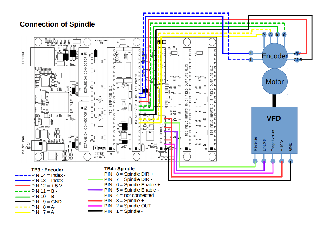
(Spindle DIR- and Spindle Enable- moved to field I/O because they needed 24v to engage, which I also had some issues with, when they where as per the connection sheet)
Also yes, I measure 10v.
Do you mean was it controlled by a potentiometer originally? for it was. its acually the control panel's spindle override i´m using for my 3 leads. Sorry if it wasn't what you meant.
Attachments:
Please Log in or Create an account to join the conversation.
- Mike_Eitel
-
- Offline
- Platinum Member
-
Less
More
- Posts: 1052
- Thank you received: 183
21 Apr 2019 11:13 #131384
by Mike_Eitel
Replied by Mike_Eitel on topic 7i76e spindle analog issues
OK, I believe you made cabling correct.
The question for the poti was based on the problem that such resistance can "short-down" the pin2 so no voltage is left over.
If you unconnect pin 2 and play with the speed parameter {spindle started} do you measure changing voltage and can you see in HALSHOW some changes on 7i76e.pin connected to ...spindle-speed-out?
You also may try to Setp that pin in a changed hal.. I think if you switch on off spindle the signal/output should jump from 0 to value..
Good luck
Please Log in or Create an account to join the conversation.
- PCW
-

- Away
- Moderator
-

Less
More
- Posts: 17968
- Thank you received: 5270
21 Apr 2019 12:18 - 21 Apr 2019 12:22 #131389
by PCW
Replied by PCW on topic 7i76e spindle analog issues
You have disconnected the analog spindle enable hal pin:
net spindle-enable => hm2_7i76e.0.7i76.0.0.output-03 #hm2_7i76e.0.7i76.0.0.spinena
hm2_7i76e.0.7i76.0.0.spinena must be true for the analog output to work
(its forced to 0 if hm2_7i76e.0.7i76.0.0.spinena is false)
Also, you can run the VFDs enable and direction pins from the 7I76 OPTO couplers,
you would power the ENA+ and DIR+ from the VFDs +24V. The drawing shows them
powered by the potentiometer power, which is I think is a mistake.
Last edit: 21 Apr 2019 12:22 by PCW.
The following user(s) said Thank You: simonmn
Please Log in or Create an account to join the conversation.
- Mike_Eitel
-
- Offline
- Platinum Member
-
Less
More
- Posts: 1052
- Thank you received: 183
21 Apr 2019 13:54 - 21 Apr 2019 13:57 #131397
by Mike_Eitel
Replied by Mike_Eitel on topic 7i76e spindle analog issues
Yes pcw,
the + connection this is not correct and not drawn that way in Norbert's drawing. And I might remember that my hy supplies more than 10v for his logic signals.
Mike
P. S.
YES, they supply 12V, but you only have to close inputs with gnd.
the + connection this is not correct and not drawn that way in Norbert's drawing. And I might remember that my hy supplies more than 10v for his logic signals.
Mike
P. S.
YES, they supply 12V, but you only have to close inputs with gnd.
Last edit: 21 Apr 2019 13:57 by Mike_Eitel. Reason: Append um of 12v
The following user(s) said Thank You: simonmn
Please Log in or Create an account to join the conversation.
- simonmn
- Offline
- Senior Member
-
Less
More
- Posts: 40
- Thank you received: 4
21 Apr 2019 15:50 #131404
by simonmn
Replied by simonmn on topic 7i76e spindle analog issues
Thanks pcw that did the trick. Although reverse is not activating.
Guess I thought I didn't need the DIR+ and enable+ until I saw the connection sheet I posted before, and thought it was a newer version.
I will look into the reverse activation tomorrow. But thanks to both of you for the help!
Guess I thought I didn't need the DIR+ and enable+ until I saw the connection sheet I posted before, and thought it was a newer version.
I will look into the reverse activation tomorrow. But thanks to both of you for the help!
Please Log in or Create an account to join the conversation.
- Mike_Eitel
-
- Offline
- Platinum Member
-
Less
More
- Posts: 1052
- Thank you received: 183
21 Apr 2019 16:29 #131408
by Mike_Eitel
Replied by Mike_Eitel on topic 7i76e spindle analog issues
Just one expirience:
My hy vfd accepts a direction change only when run signal transit from low to high.
My hy vfd accepts a direction change only when run signal transit from low to high.
Please Log in or Create an account to join the conversation.
- simonmn
- Offline
- Senior Member
-
Less
More
- Posts: 40
- Thank you received: 4
22 Apr 2019 12:24 #131493
by simonmn
Replied by simonmn on topic 7i76e spindle analog issues
Hi again
So I found out the issue with the spindle not being able to reverse.
Halmeter(Halshow?) shows me that both spindle enable and spindle dir turns on at reverse command, and my VFD doesn't like that. It just "turns on" with no rpm.
How would I go about changing this in Hal, if spinena is required for analog control?
Please Log in or Create an account to join the conversation.
- simonmn
- Offline
- Senior Member
-
Less
More
- Posts: 40
- Thank you received: 4
23 Apr 2019 16:02 #131661
by simonmn
Replied by simonmn on topic 7i76e spindle analog issues
I found myself a solution.
In my spindle hal section I replaced:With:
So its much like before, with forward and reverse signals coming from field I/O, except spindle enable pin is now left unconnected.
Just a little curious, is this find/safe enough?
Anyway thank you guys for the help!
In my spindle hal section I replaced:
net spindle-output      => hm2_7i76e.0.7i76.0.0.spinout
net spindle-enable     => hm2_7i76e.0.7i76.0.0.spinena
net spindle-ccw => hm2_7i76e.0.7i76.0.0.spindirnet spindle-output => hm2_7i76e.0.7i76.0.0.spinout
net spindle-enable => hm2_7i76e.0.7i76.0.0.spinena
#net spindle-ccw => hm2_7i76e.0.7i76.0.0.spindir
net spindle-cw => hm2_7i76e.0.7i76.0.0.output-03
net spindle-ccw => hm2_7i76e.0.7i76.0.0.output-04So its much like before, with forward and reverse signals coming from field I/O, except spindle enable pin is now left unconnected.
Just a little curious, is this find/safe enough?
Anyway thank you guys for the help!
Please Log in or Create an account to join the conversation.
Time to create page: 2.238 seconds