Mill Retrofit with Fanuc DC Drives
- tbrasselle
- Offline
- New Member
-

Less
More
- Posts: 11
- Thank you received: 0
17 May 2026 01:22 #346449
by tbrasselle
Replied by tbrasselle on topic Mill Retrofit with Fanuc DC Drives
I just tried increasing D and it seemed to increase the amplitude of the oscillation as I increased the value.
I also wanted to verify the encoder is working correctly even though it appears to be working correctly in halscope. I hooked it up to an oscilloscope and got a chart I wasn't expecting. Channel A seems to be stopping at 0V on both the rising and following edge. channel B seems correct and bounced between +5V and -5V.
Would this cause any issues with counting on the mesa card?
Please Log in or Create an account to join the conversation.
- PCW
-

- Offline
- Moderator
-

Less
More
- Posts: 17937
- Thank you received: 5255
17 May 2026 16:42 - 17 May 2026 16:43 #346463
by PCW
Replied by PCW on topic Mill Retrofit with Fanuc DC Drives
Are you measuring the encoder signals against ground?
(you cannot measure differential signals on an oscilloscope without a differential probe)
(you cannot measure differential signals on an oscilloscope without a differential probe)
Last edit: 17 May 2026 16:43 by PCW.
Please Log in or Create an account to join the conversation.
- tbrasselle
- Offline
- New Member
-
Less
More
- Posts: 11
- Thank you received: 0
18 May 2026 00:03 #346468
by tbrasselle
Replied by tbrasselle on topic Mill Retrofit with Fanuc DC Drives
I was measuring it against the compliment. I had the probe on channel A and the ground on the probe clamped to the inverse channel A. Same thing for channel B.
Viewing channel a and channel b in HALSCOPE everything looks normal. So I’d assume this isn’t actually the issue either.
Viewing channel a and channel b in HALSCOPE everything looks normal. So I’d assume this isn’t actually the issue either.
Please Log in or Create an account to join the conversation.
- PCW
-
- Offline
- Moderator
-
Less
More
- Posts: 17937
- Thank you received: 5255
18 May 2026 00:24 - 18 May 2026 00:27 #346469
by PCW
Replied by PCW on topic Mill Retrofit with Fanuc DC Drives
You cannot do this without two differential probes.
Measure the A,B signals relative to ground.
But as you said I don't think this is the issue as long as the position
readout is correct.
Measure the A,B signals relative to ground.
But as you said I don't think this is the issue as long as the position
readout is correct.
Last edit: 18 May 2026 00:27 by PCW.
Please Log in or Create an account to join the conversation.
- tommylight
-

- Offline
- Moderator
-
Less
More
- Posts: 21665
- Thank you received: 7400
18 May 2026 00:25 #346470
by tommylight
Replied by tommylight on topic Mill Retrofit with Fanuc DC Drives
Measure between gnd and each channel.
Please Log in or Create an account to join the conversation.
- PCW
-
- Offline
- Moderator
-
Less
More
- Posts: 17937
- Thank you received: 5255
18 May 2026 16:22 #346479
by PCW
Replied by PCW on topic Mill Retrofit with Fanuc DC Drives
Are the motors connected to the linear axis?
This will affect the loop stability
Can you change the velocity loop gain on the drives?
This will affect the loop stability
Can you change the velocity loop gain on the drives?
Please Log in or Create an account to join the conversation.
- tbrasselle
- Offline
- New Member
-
Less
More
- Posts: 11
- Thank you received: 0
19 May 2026 01:38 #346488
by tbrasselle
Replied by tbrasselle on topic Mill Retrofit with Fanuc DC Drives
I did have the motor disconnected from the ballscrew initially. I've now connected it back and the problem has not gone away. I've attached a halscope screenshot showing the current status. when i enable the drive it oscillates, starts to smooth out, then runs away.
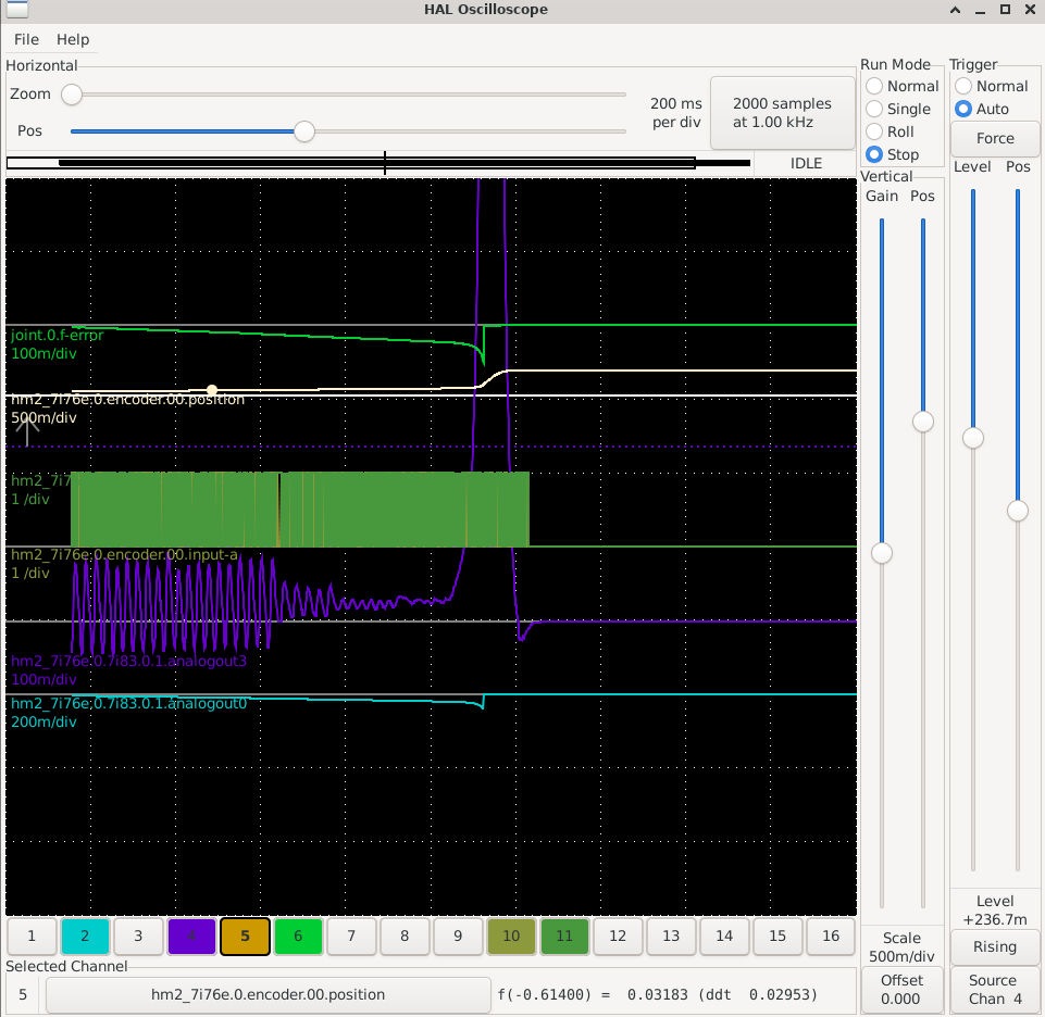
I can adjust the velocity loop gain on the drive but i have been hesitant to do that. the drive and motor were working as is with the Fanuc controller before I disconnected them.
I can adjust the velocity loop gain on the drive but i have been hesitant to do that. the drive and motor were working as is with the Fanuc controller before I disconnected them.
Attachments:
Please Log in or Create an account to join the conversation.
- PCW
-
- Offline
- Moderator
-
Less
More
- Posts: 17937
- Thank you received: 5255
19 May 2026 04:58 #346491
by PCW
Replied by PCW on topic Mill Retrofit with Fanuc DC Drives
The runaway suggests that possibly one of the feedback loops is reversed.
Please Log in or Create an account to join the conversation.
- tbrasselle
- Offline
- New Member
-
Less
More
- Posts: 11
- Thank you received: 0
20 May 2026 00:29 - 20 May 2026 00:50 #346504
by tbrasselle
Replied by tbrasselle on topic Mill Retrofit with Fanuc DC Drives
The runaway only happens when I add a small amount of gain to P.
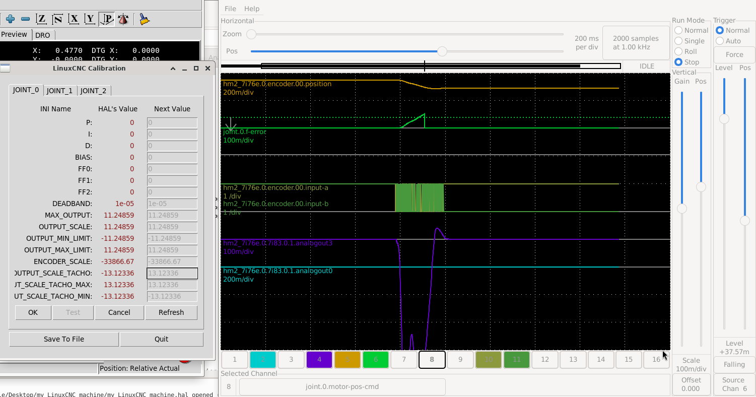
I've backed up a little to triple check that I have both outputs scaled and the correct directions. The original Fanuc manuals show the test points and expected scales of the input signals for the drives.
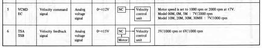
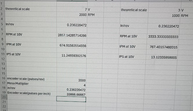
The machine moves 0.2362 inches per revolution and the encoders have 2000 pulses/rev. I used that to calculate an encoder scale which does need to be negative to make the DRO move the correct direction. I then calculated the ratios to get the inches per second of movement that should equate to 10V for both the velocity command and tachometer.
Next I wanted to measure the actual values at the drive. I have the oscilloscope hooked up to the virtual tach signal(output3) and the velocity command signal(output0). I set the PID values back to zero for this test. These images are of the halscope and oscilloscope with a positive value in the tachometer output scale. The pink trace is the tachometer signal(output3) and the yellow trace is the velocity signal(output0).
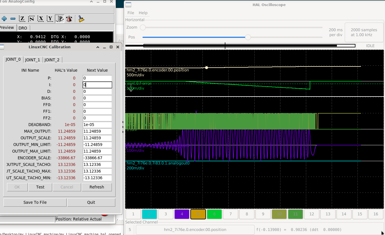
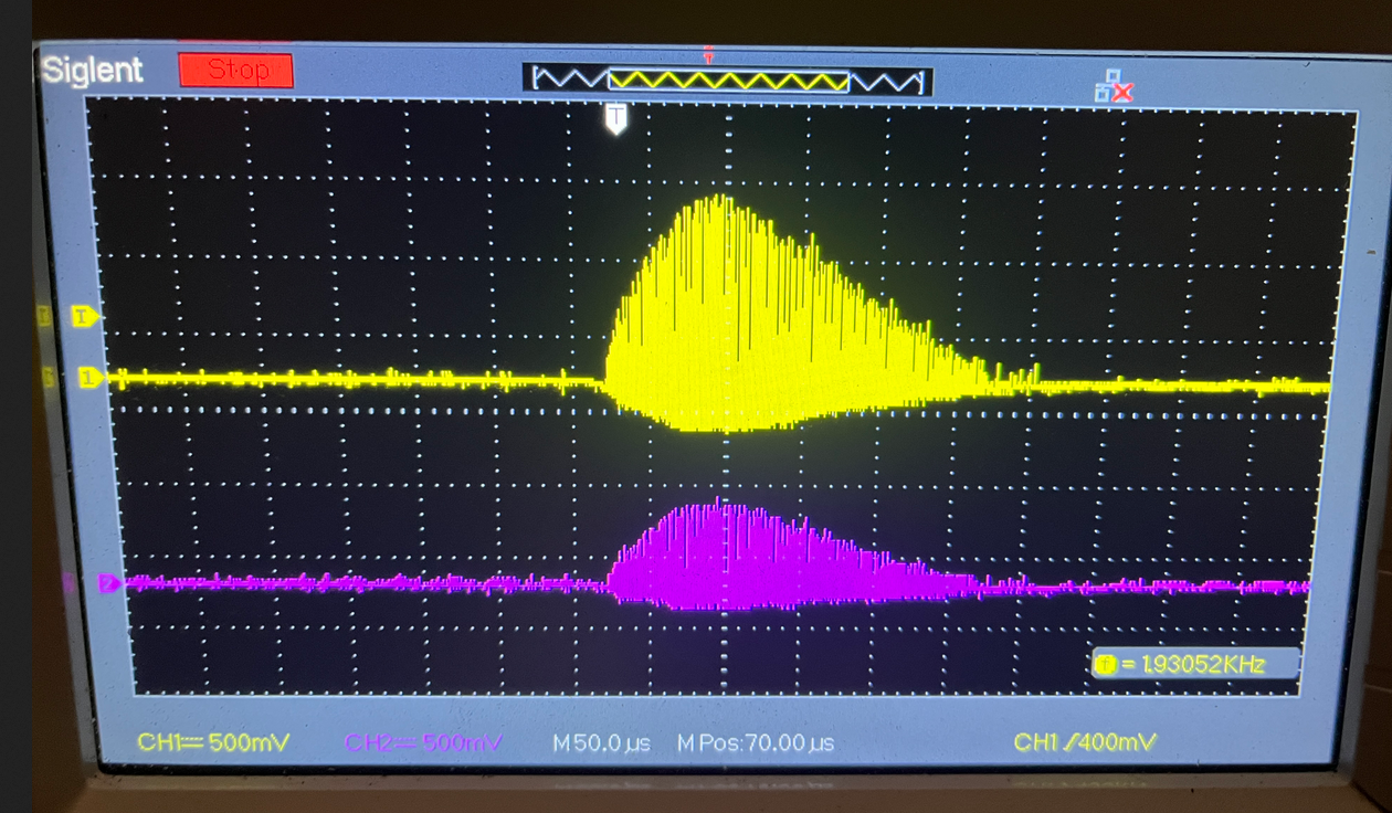
These images are with a negative tachometer output.
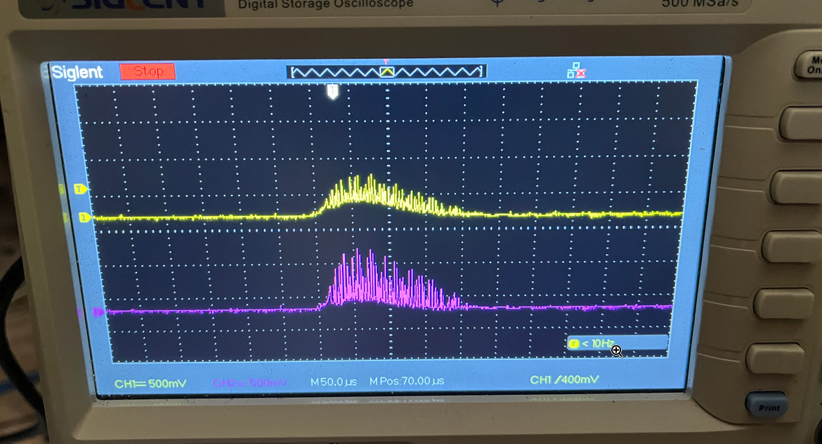
With the PID values set to zero, shouldn't analogout0 be zero? it seems to follow analogout3. I've double checked that I dont have a short between the two.
I've backed up a little to triple check that I have both outputs scaled and the correct directions. The original Fanuc manuals show the test points and expected scales of the input signals for the drives.
The machine moves 0.2362 inches per revolution and the encoders have 2000 pulses/rev. I used that to calculate an encoder scale which does need to be negative to make the DRO move the correct direction. I then calculated the ratios to get the inches per second of movement that should equate to 10V for both the velocity command and tachometer.
Next I wanted to measure the actual values at the drive. I have the oscilloscope hooked up to the virtual tach signal(output3) and the velocity command signal(output0). I set the PID values back to zero for this test. These images are of the halscope and oscilloscope with a positive value in the tachometer output scale. The pink trace is the tachometer signal(output3) and the yellow trace is the velocity signal(output0).
These images are with a negative tachometer output.
With the PID values set to zero, shouldn't analogout0 be zero? it seems to follow analogout3. I've double checked that I dont have a short between the two.
Last edit: 20 May 2026 00:50 by tbrasselle.
Please Log in or Create an account to join the conversation.
- PCW
-
- Offline
- Moderator
-
Less
More
- Posts: 17937
- Thank you received: 5255
20 May 2026 01:54 #346505
by PCW
Replied by PCW on topic Mill Retrofit with Fanuc DC Drives
Is it possible that there is a grounding issue?
Did the original system use a tachometer?
If so , it would be floating which may be a requirement of the drives input circuit
Did the original system use a tachometer?
If so , it would be floating which may be a requirement of the drives input circuit
Please Log in or Create an account to join the conversation.
Time to create page: 0.270 seconds