

- Posts: 17533
- Thank you received: 5334
Mill Retrofit with Fanuc DC Drives
5 months 2 weeks ago #346434
by PCW
Replied by PCW on topic Mill Retrofit with Fanuc DC Drives
I suspect its something with the tachometer emulation or connections to the Fanuc drive
How did the original drive get velocity feedback?
How did the original drive get velocity feedback?
Please Log in or Create an account to join the conversation.
- tbrasselle
- Topic Author
- Offline
- New Member
-

Less
More
- Posts: 11
- Thank you received: 0
5 months 2 weeks ago #346436
by tbrasselle
Replied by tbrasselle on topic Mill Retrofit with Fanuc DC Drives
Thanks again for help. I swapped both analogoutput0 and analogoutput3 to RG58 cable that I had laying around and had the same results. I also double checked the ground and shielding on the original wiring. i had disconnected one of the grounds but reconnecting it also did not change anything.It looks like the oscillation is at about 33Hz so I don't think it is from the main power. Another note, I change the base period on the servothred from 1000000ns to 800000ns to see if that changed anything. it seems to change the frequency slightly but it no affect on the amplitude.

Please Log in or Create an account to join the conversation.
- tbrasselle
- Topic Author
- Offline
- New Member
-
Less
More
- Posts: 11
- Thank you received: 0
5 months 2 weeks ago #346446
by tbrasselle
Replied by tbrasselle on topic Mill Retrofit with Fanuc DC Drives
It was originally set up with a virtual tach signal coming from the Fanuc controller. The original manuals showed a tach voltage of 3V/1000RPM which I should have. I ran the motor on a bench power supply, bypassed the drive, calculated the motor speed with an oscilloscope connected to one of the encoder pins, then measured the output voltage on analogout3. my output seems to be scaled correctly and the voltages match the original drive documentation.
I believe I have the scaling and direction correct, but am wondering if I am running into some type of resonance between the virtual tach and commanded velocity.
Does that seem possible or correct?
I believe I have the scaling and direction correct, but am wondering if I am running into some type of resonance between the virtual tach and commanded velocity.
Does that seem possible or correct?
Please Log in or Create an account to join the conversation.
5 months 2 weeks ago #346447
by PCW
Replied by PCW on topic Mill Retrofit with Fanuc DC Drives
Hard t tell but it does look the the velocity loop is unstabley
Just as a test have you tried adding some D term to the PID?
Just as a test have you tried adding some D term to the PID?
Please Log in or Create an account to join the conversation.
- tbrasselle
- Topic Author
- Offline
- New Member
-
Less
More
- Posts: 11
- Thank you received: 0
5 months 2 weeks ago #346449
by tbrasselle
Replied by tbrasselle on topic Mill Retrofit with Fanuc DC Drives
I just tried increasing D and it seemed to increase the amplitude of the oscillation as I increased the value.
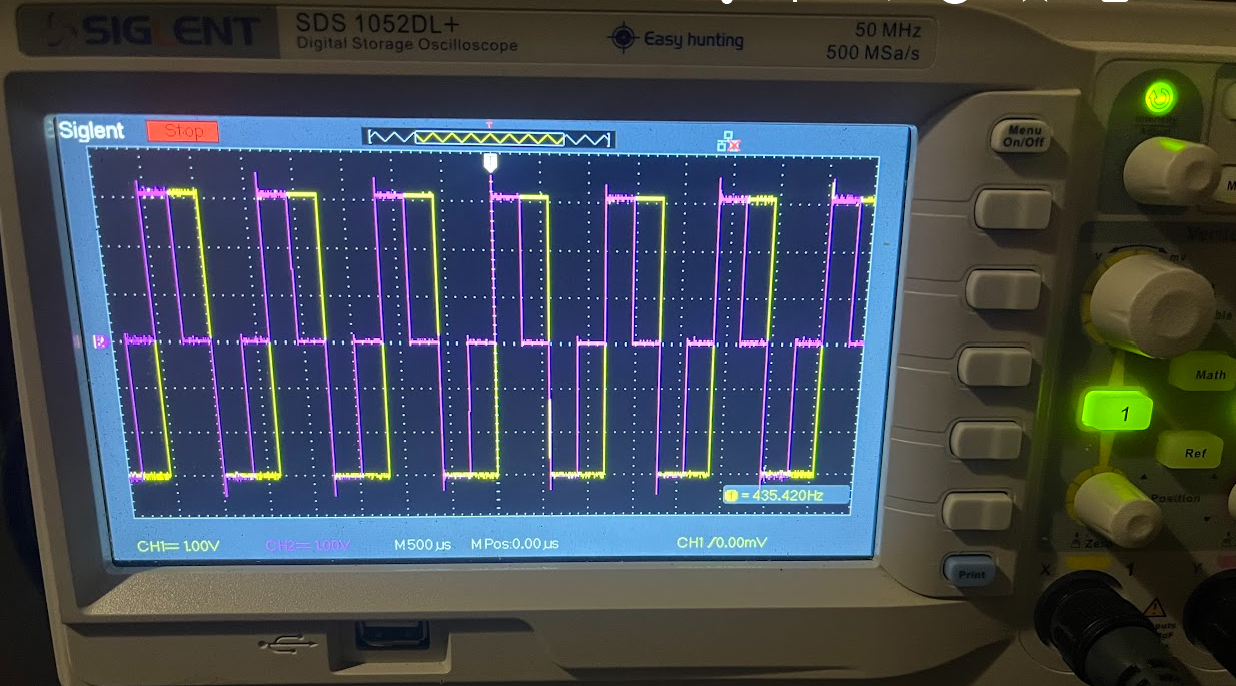
I also wanted to verify the encoder is working correctly even though it appears to be working correctly in halscope. I hooked it up to an oscilloscope and got a chart I wasn't expecting. Channel A seems to be stopping at 0V on both the rising and following edge. channel B seems correct and bounced between +5V and -5V.
Would this cause any issues with counting on the mesa card?
I also wanted to verify the encoder is working correctly even though it appears to be working correctly in halscope. I hooked it up to an oscilloscope and got a chart I wasn't expecting. Channel A seems to be stopping at 0V on both the rising and following edge. channel B seems correct and bounced between +5V and -5V.
Would this cause any issues with counting on the mesa card?
Please Log in or Create an account to join the conversation.
5 months 2 weeks ago - 5 months 2 weeks ago #346463
by PCW
Replied by PCW on topic Mill Retrofit with Fanuc DC Drives
Are you measuring the encoder signals against ground?
(you cannot measure differential signals on an oscilloscope without a differential probe)
(you cannot measure differential signals on an oscilloscope without a differential probe)
Last edit: 5 months 2 weeks ago by PCW.
Please Log in or Create an account to join the conversation.
Time to create page: 0.056 seconds