- Configuring LinuxCNC
- Advanced Configuration
- ClassicLadder
- Mazak Slant-turn 15 CNC Lathe Turret Logic
Mazak Slant-turn 15 CNC Lathe Turret Logic
- sqmathlete
- Offline
- Premium Member
-

- Posts: 118
- Thank you received: 18
I am working on retrofitting a Mazak Slant-Turn 15 CNC lathe, and need some help duplicating the ladder logic for
- m6 tool change, 10 position turret, each position has it's own limit switch, fwd rotation only. From observation i.e when the machine use to run, if the turret didn't either clamp within a specific time (approximately 1.5 sec) or the tool confirmation switch wasn't on when the turret was clamped then the turret would unclamp and cycle through again.
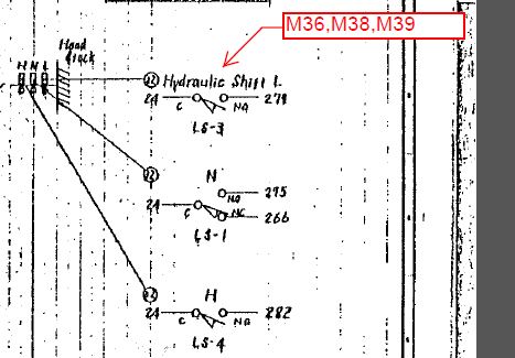
Not locking in the correct position or on time could be caused by low hydraulic pressure or worse case misalignment of the cervic coupling. - gear shift m36 neutral, m38 low, m39 high.
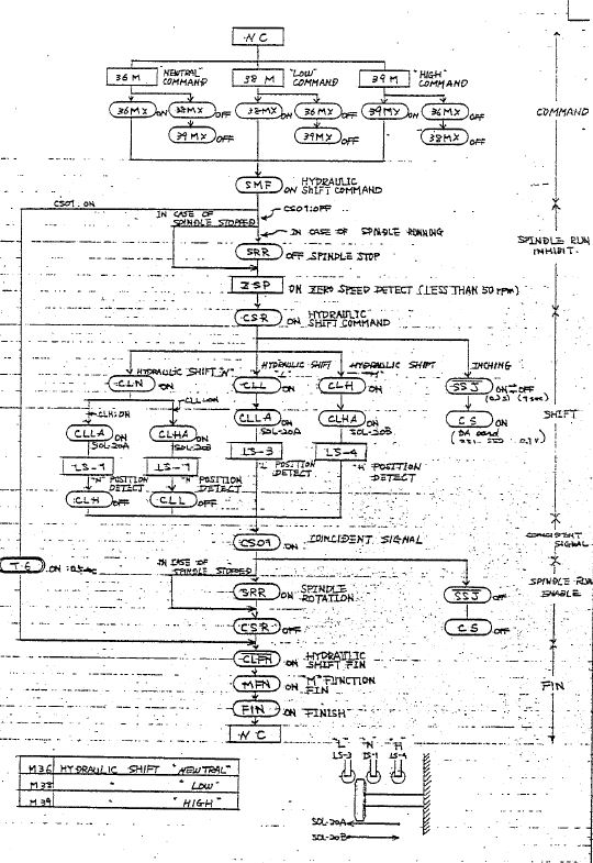
In the block diagram , there is an "inching" function that slowly rotates the spindle and turns the solenoid on/off for a specific amount of time. I think was to help it shift gear but, i'm not sure. Also, I'm hoping that eventually this could be used with a gearchange component and remapped S code to automatically select the gear based on spindle speed...One thing at a time I know
The original block/flow diagrams are attached. I have the remap all set-up for these codes and a glade-vcp that simulates the tool confirmation reed switches, and use bits to simulate limit switches but I can't quite seem to get the logic right in classicladder. Is there a logic guru out there that can sort this out?
Thanks in advance,
Dan
Please Log in or Create an account to join the conversation.
- sivaraj
- Offline
- Senior Member
-

- Posts: 50
- Thank you received: 25
1. Unclamp Solenoid SOL1
2. Turret Rotation Fast SOL2A
3. Turret Rotation Slow SOL2B
2-inputs on turret rotation status and 10 inputs for turret position
1.Turret Clamped TCLF
2.Turret index position (ok to clamp position) INDF-LS
+
3.Turret actual position sensor. 10 inputs in your case
It looks to me you are converting a old Fanuc 6T Mazak of around 80's and it was without Fanuc PMC ladder. They did machine logic with hardware relays.
Turret logic:
In your case turret has sensing for Turret clamp TCLF.
But no physical sensor for turret unclamp.
So in internal hardware logic they make condition , so that
Turret unclamped confirmation = Turret unclamp solenoid SOL1 ON+Turret Clamped TCLF switch is off +time 1.5sec .
Assume this signal Turret unclamped (TUCLF). Or ok for turret rotation
Once (TUCLF) is ready may enable Turret rotation solenoid.
There are two turret rotation solenoids.
one slow and other for normal or fast
Selection of SOL2A or 2B is decided by (PLC) based on the number of station between current turret position and your required position in AUTO tool command Txxx . If the station difference (distance to go) is < or =1 then only slow solenoid has to be on.
This is to ensure that turret will stop at consistent position during clamping at index position .
Slow Rotation Solenoid should switch off after INDF-LS is switched on.
This is like OK to clamp position.
Now switch off the unclamp solenoid SOL1.
Note that Turret should clamp only when INDF-LS is on.
Otherwise it should keep unclamp solenoid ON as other are improper position.
Regarding the 10 turret position sensor inputs you must convert it into bcd code to compare actual position and T- command
Gear change:
You have 3 position Gear1,Gear-2, Neutral
Gear shifter cannot move to required position unless gears are aligned to move.
So it is normal practice to oscillate the spindle while gear shifting (command value should be slow like 5 to 10 rpm)
If you are using ladder logic you may require minimum 3 or 4 timers
Like timer for Spindle index on /spindle index off / restart index timer / solenoid on time
You must enable the solenoid only when spindle index is off (spindle not enabled for oscillation).
If no confirmation of the required gear position then it should repeat the spindle index sequence
Even you can make with for/rev alternatively with different logic for oscillation.
Hope this helps
Please Log in or Create an account to join the conversation.
- sqmathlete
- Offline
- Premium Member
-
- Posts: 118
- Thank you received: 18
Thanks for your quick response. You are right on, 1984, Fanuc 6TB control, and a whole wack o' relays.
If the station difference (distance to go) is < or =1 then only slow solenoid has to be on.
I am a bit confused though...to me it reads as the slow rotation solenoid (FSLW) and the rotation solenoid (FRW) are turned off in the same step as the un-clamp solenoid (TUC). Which could? make sense depending on how the hydraulic valves are actuated.
Also, please correct me if this does not make sense, at one time TCLF was a relay but now we are using it as a "signal" to indicate the completion of a step, i.e. that the turret is either clamped or un-clamped. No?
I am going to have another look at my turret logic and compare it to your steps. Needless to say I am very hesitant to wire this part up without having a bullet proof logic routine that can handle an error in proper fashion...
Kind regards,
Dan
Please Log in or Create an account to join the conversation.
- sivaraj
- Offline
- Senior Member
-
- Posts: 50
- Thank you received: 25
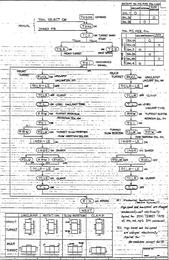
Your flowchart meant for twin turret machine .Front /Rear
For you case Slantturn 15 has only Front turret
The Flowchart for Front turret rotation :
1.FUCL > Front turret unclamp solenoid is on
2.TCLF-LS >Turret unclamp limit switch goes OFF
3.TCL >Turret clamp signal off or is unclamped
4.T-L > timer to unclamp un-clamp confirmation
5.T01 >whether goal distance is < or =1
it decides slow speed or high speed
*1 note says for disk type turret it is mechanical.
So I hope it will be FRW only for fast and FRW+FSLW for slow rotation
6.Once turret rotation in slow speed it will rotates till finding INDF index signal is ON
7.If INDF=1 It switches off all three solinoids FSLW FRW FUCL
8.TCLF-LS >Turret clamp limit switch signal will come on
9.TCL> tool clamp confirmation
Please Log in or Create an account to join the conversation.
- sqmathlete
- Offline
- Premium Member
-
- Posts: 118
- Thank you received: 18
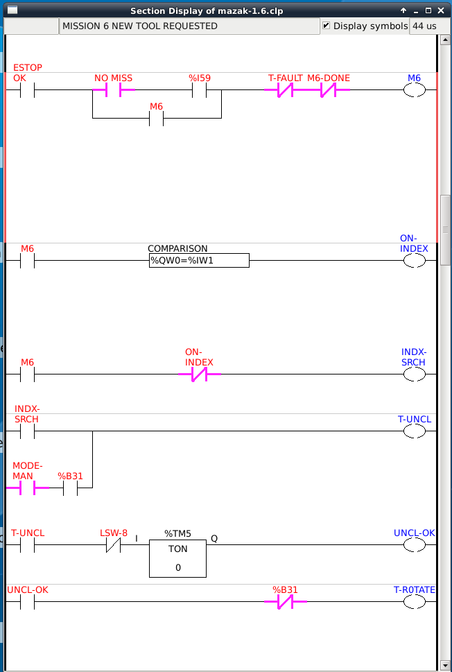
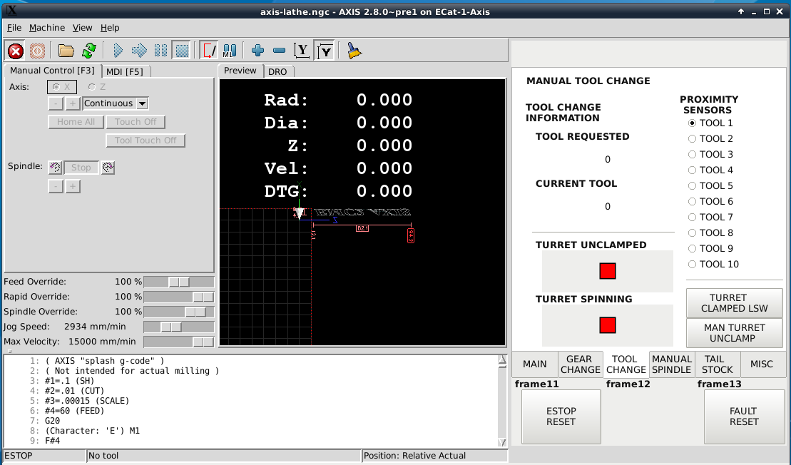
The proximity switches are simulated by radio buttons in the gui so that only one can be active at a time.
The higher level logic is controlled by a mission pattern. Mission 6 (M6) is called by a tool change request (classicladder.0.in-59) and ended when the tool is in position (T-IN-POS).
The M6-Done coil is delayed so that linuxcnc has time to acknowledge that the tool change is done before M6 is reset. Also by not sealing in the index comparison, if for some reason the index switch is not on when the turret is clamped the cycle of unclamp=>rotate=>slow-rotate starts again...I think.
The fault coil at this pint doesn't do much but, I think it could be used to time the closing of the turret?
An unseen counter takes care of looping from tool 10 to tool 1
Any thoughts or questions?
P.s. I'm still working on the gear change.


Please Log in or Create an account to join the conversation.
- johnmc1
- Offline
- Senior Member
-
- Posts: 78
- Thank you received: 21
Is the ladder logic for the mazak m3 twin turret similar
for the mazak m3 the sequence is as followers when a tool is called the correct turret lifts > turret unclamp signal> highspeed rotation when correct tool > inputs > slow rotation solenoid > then tool clamps there is also a time out if tool change not completed
cheers johnmc1
Please Log in or Create an account to join the conversation.
- sqmathlete
- Offline
- Premium Member
-
- Posts: 118
- Thank you received: 18
The sequence does sound similar to the slant-turn (which was available with twin turrets). Unfortunately, I am not familar with the M3, so I can't really say. Is the turret hydraulic?for the mazak m3 the sequence is as followers when a tool is called the correct turret lifts > turret unclamp signal> highspeed rotation when correct tool > inputs > slow rotation solenoid > then tool clamps
In the logic above, I added the time out fault as a potential way of dealing with a turret fault but, I am now thinking that you would probably just let the turret keep looping around until it finds its position.there is also a time out if tool change not completed
Dan
Please Log in or Create an account to join the conversation.
- johnmc1
- Offline
- Senior Member
-
- Posts: 78
- Thank you received: 21
that indicate when to slow turret rotation for the programmed tool .
Your system appears, tool position logic , Tn < or =1 to signal slow rotation . as per "sivaraj replied the topic"
cheers john
Please Log in or Create an account to join the conversation.
- Configuring LinuxCNC
- Advanced Configuration
- ClassicLadder
- Mazak Slant-turn 15 CNC Lathe Turret Logic