Current turning capabilities status

More
13 years 2 weeks ago #40039 by jtc
Thanks andypugh, we just limit the speed and acelaration on the drive. for now just works fine.

So, the current status of the machine is: we have almost the hardware needed to complete the machine and at this point we have to start testing seriously linuxcnc capabilities.

for now there are 2 problems. in the axis gui, the plans is to invert the X axis, not inverted by geometry (already make this in Z axis), but on the screen itself. now the X axis is below then the centrer line(Z axis), but we want that in the upper part, just above Z axis.

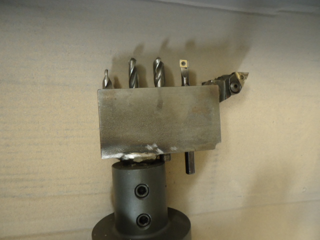
the second problem, for example, we have a holder that use more than one tip, like this:


is this possible? how can it be defined in the tool table? can have more that one tip per pocket?

Tnks,

João

Please Log in or Create an account to join the conversation.

More
13 years 2 weeks ago #40040 by andypugh

jtc wrote: for now there are 2 problems. in the axis gui, the plans is to invert the X axis, not inverted by geometry (already make this in Z axis), but on the screen itself. now the X axis is below then the centrer line(Z axis), but we want that in the upper part, just above Z axis.

In this thread: www.linuxcnc.org/emc2/index.php/english/...tools?start=10#24959 it was discovered that using coordinate-system rotation works well.

can have more that one tip per pocket?

Unfortunately not. Which is rather irritating. The next version of the tool table will support this. (If my changes are accepted). But this is likely to take quite a long time.

A workaround may be to configure your toolchanger in such a way that pockets (or tools) 001, 101, 201, 301 etc are all interpreted as being in the same place on the tool carousel.

I have a feeling that, contrary to what the docs say, the "Pocket number" in the current tool table can not be > 56. However I _think_ that it is possible to configure a tool-changer to act on the value on the tool-number request rather than the pocket number request.

Please Log in or Create an account to join the conversation.

More
13 years 1 week ago #40059 by cmorley
You could use multiple offsets with the same tool number - You may need the fanuc tool patch to do this though...

Chris M

Please Log in or Create an account to join the conversation.

More
13 years 1 week ago #40069 by emcPT
I had a feeling that this was already solved, or at least covered in some form.
After cmorley wrote "fanuc tool path", google gave me:

sourceforge.net/p/emc/feature-requests/103/

This is dated more than 1 year ago, so probably the patch is now better/more stable. Were can I find (or know if exists) an updated version for the patch?

Unfortunately we do not have the knowledge how linuxcnc is structured / updated / contributed, and for example if cmorley did not posted, probably we would never knew about it. I hope not to sound ungrateful (because I am really not).

We already have all the control panel working and servos working. It is really nice to use the machine with the wheel jog !
Regarding the rotation of the coordinate system as Andy pointed out, it works fine (at least it looks that way).

We are now close to the first testing. For now it seams that the tool call is out priority and to check if the tool compensation (G41 G42) is really working as we use it extensively.

Basically we are working on this for 8 months.
All hardware is set up except the VFD that we had to acquire one more powerful than the one that we first started to test with. Main motor is 20kw @ 200V. As it was hard to get one compatible voltage 200V (we are in Europe). Since modern VFD can limit the output voltage, in theory, a 40Kw @ 400V would be ok to delivery the same amperage that the motor may require. The one that we could bought (ebay) was for 100kw @ 400V :ohmy: . Lets hope that my theory for limiting the output voltage is true, and that it will trully limit the output voltage not to damage the motor. At least I will not see "Over current" in the VFD :)

Please Log in or Create an account to join the conversation.

More
13 years 1 week ago #40104 by emcPT
Today I tested how the CSS works and the tool compensation modes. Both are important for my use.
All tests were done on simulation.

The CSS appears to be fine, but the compensation probably have some issue that I do not understand.
I tested the simple code below:
Code:
G18 G7 T101M6 (outside cutting tool radius 0.2) G00 X20 Z5 M3 G96 D2500 S200 (max 2500, surface speed 300) G95 (feed per revolution) G42 G1 Z1 F0.1 X22 Z0 X25 Z-2 X35 Z-5 Z-10 G0 X45 G40 Z5 M02

Nothing strange about it. The tool 101 is well defined with a radius of 0.2mm (that on the tool table is supposedly to be in diameter. The value on the tool table is 0.2 and seams to be ok). The problem is that as can be seen on the picture attached, that the movement from point X35 Z-5 to point X35 Z-10, the machine is in diameter X35.4 instead of X35 (I know that 35.4 = 35 + 0.2 + 0.2 that could be related with the tool radius).
If the movement is along the Z axis, the commanded position in X should match the tool position even if the compensation is on. In lathes the DRO should display the imaginary tool tip. It looks that the DRO is showing the tool tip center like in mills, that is inappropriate for lathes.

Can someone please inform if G41 G42 is really working as stated on several linuxcnc documentation for lathes? I am not sure if I am missing some config.

A bit about the same issue:
The info on the following link is wrong. The X+ arrow is swapped. Linuxcnc toolpath is correct, and behaves differently from the following link.
www.linuxcnc.org/docs/2.4/html/lathe_lathe-user.html#r1

Please Log in or Create an account to join the conversation.

More
13 years 1 week ago #40105 by emcPT
The same error is here:
wiki.linuxcnc.org/cgi-bin/wiki.pl?Lathe_Advanced_Features

and the correct tooltip direction can be seen on the file attached.

Please Log in or Create an account to join the conversation.

Time to create page: 0.082 seconds
Powered by Kunena Forum