Disabling servo amps.
- sliptonic
- Offline
- Premium Member
-

Less
More
- Posts: 132
- Thank you received: 20
07 Jun 2016 17:44 #75650
by sliptonic
Disabling servo amps. was created by sliptonic
I have AMC 30A8 amps that I drive from a 5i25/7i77. Now I'm trying to disable the amps when the machine isn't enabled. The amps are normally enabled and disabled by connecting a pin to ground. From the manual: "TTL level (+5 V) inhibit/enable input. Leave open to enable drive. Pull to ground to inhibit drive. Inhibit turns off all power devices."
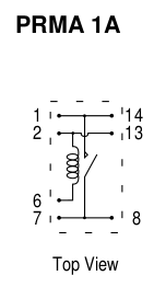
From conversations with PCW, I believe I have to use a relay to invert the enable logic but I'm not entirely sure how to do that. I have this 24V reed relay:
If I'm understanding the other posts I've read, I need to send 24V to the ena0+, ena0- to trigger the relay, and connect the inhibit+ to the ground through the NC contacts of the relay?
I have these two lines in hal:
net x-enable axis.0.amp-enable-out
net x-enable hm2_5i25.0.7i77.0.1.analogena
Am I in the right ballpark? I suck at electronics so thanks in advance for using small words and/or colorful pictures.
The following user(s) said Thank You: Catch22
Please Log in or Create an account to join the conversation.
- PCW
-

- Away
- Moderator
-

Less
More
- Posts: 17680
- Thank you received: 5170
07 Jun 2016 17:58 #75651
by PCW
Replied by PCW on topic Disabling servo amps.
That looks like a single Normally Open (NO)
contact, you will need a normally closed contact
relay for this purpose
contact, you will need a normally closed contact
relay for this purpose
The following user(s) said Thank You: Catch22
Please Log in or Create an account to join the conversation.
- sliptonic
- Offline
- Premium Member
-

Less
More
- Posts: 132
- Thank you received: 20
08 Jun 2016 00:33 #75663
by sliptonic
Replied by sliptonic on topic Disabling servo amps.
Of course. 
I've replaced it with NC relay which I've wired up. Powering the coil enables the amps as expected.
Now I've got 24V from field power to ENA0+. Connecting the coil to ENA0- / GND does nothing.
Connecting to ENA0- and GND on the field power flips the relay but toggling hm2_5125.0.7i77.0.1.analogena doesn't change the state.
Where am I messed up in my wiring and config?
The following user(s) said Thank You: Catch22
Please Log in or Create an account to join the conversation.
- PCW
-

- Away
- Moderator
-

Less
More
- Posts: 17680
- Thank you received: 5170
08 Jun 2016 04:06 #75668
by PCW
Replied by PCW on topic Disabling servo amps.
You need to be a bit careful here or you can damage the ENA outputs
The relay needs to draw 50 mA or less and the relay coil must have a flyback diode
Wiring should be:
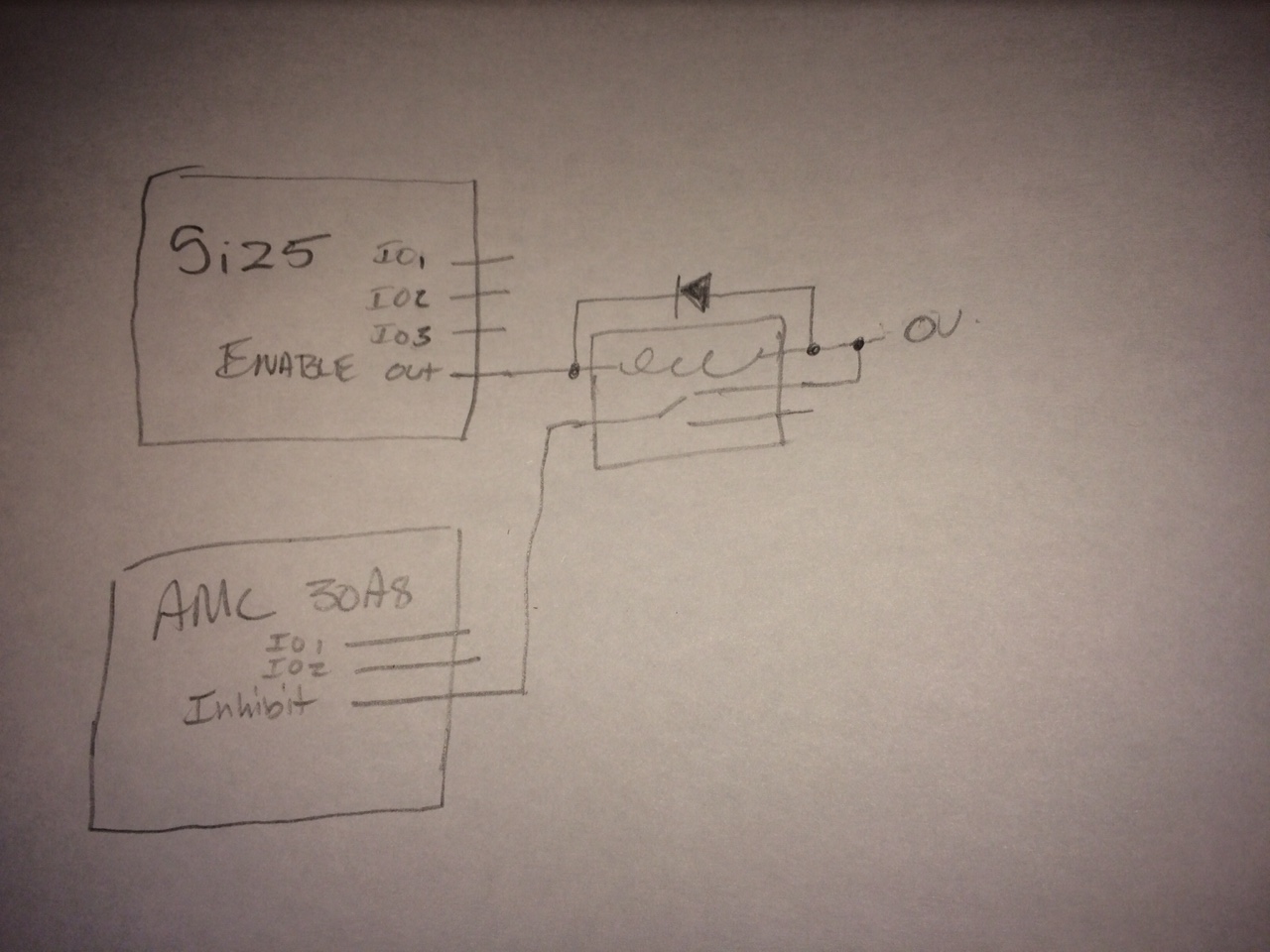
+24V --> Relay coil 1 and flyback diode cathode --> relay coil 2 and flyback diode anode --> ENA+ --> ENA-
24V GND
The relay needs to draw 50 mA or less and the relay coil must have a flyback diode
Wiring should be:
+24V --> Relay coil 1 and flyback diode cathode --> relay coil 2 and flyback diode anode --> ENA+ --> ENA-
24V GND
The following user(s) said Thank You: Catch22
Please Log in or Create an account to join the conversation.
- sliptonic
- Offline
- Premium Member
-

Less
More
- Posts: 132
- Thank you received: 20
08 Jun 2016 15:02 #75688
by sliptonic
O.k. The diode makes sense to me but I don't understand the connection from ENA+ to ENA-.
Replied by sliptonic on topic Disabling servo amps.
You need to be a bit careful here or you can damage the ENA outputs
The relay needs to draw 50 mA or less and the relay coil must have a flyback diode
Wiring should be:
+24V --> Relay coil 1 and flyback diode cathode --> relay coil 2 and flyback diode anode --> ENA+ --> ENA-
24V GND
O.k. The diode makes sense to me but I don't understand the connection from ENA+ to ENA-.
The following user(s) said Thank You: Catch22
Please Log in or Create an account to join the conversation.
- PCW
-

- Away
- Moderator
-

Less
More
- Posts: 17680
- Thank you received: 5170
08 Jun 2016 15:56 - 08 Jun 2016 16:02 #75690
by PCW
Replied by PCW on topic Disabling servo amps.
The ENA+ and ENA- path is made when the switch is on (the list shows the entire current path)
As a side note, the reason I would wire it this way instead of connecting ENA+ to +24V and ENA- to the relay
is that if ENA+ is connected to +24V, an accidental short of ENA- to ground will destroy the optocoupler
As a side note, the reason I would wire it this way instead of connecting ENA+ to +24V and ENA- to the relay
is that if ENA+ is connected to +24V, an accidental short of ENA- to ground will destroy the optocoupler
Last edit: 08 Jun 2016 16:02 by PCW.
The following user(s) said Thank You: sliptonic
Please Log in or Create an account to join the conversation.
- kornphlake79
- Offline
- Senior Member
-

Less
More
- Posts: 52
- Thank you received: 10
09 Jun 2016 04:48 - 09 Jun 2016 04:58 #75708
by kornphlake79
Replied by kornphlake79 on topic Disabling servo amps.
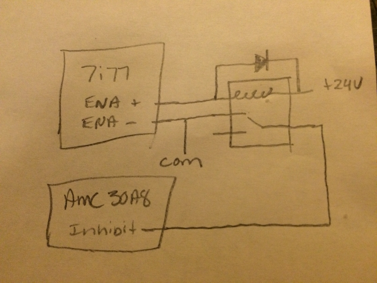
If I'm reading the snippets from your instruction manuals correctly you need a 5v relay, not a 24v relay. Your 5i25 will output a 5v signal to enable the drive, so you'll need a relay with a 5v coil right? The relay will switch the enable to ground to inhibit the drive. You'll put a diode across the coil terminals. Roughly as shown in this diagram, I show a SPDT relay because they're more common than SPST relays, and more versatile, you could use a NC SPST relay though. If you wanted to go one step further you could put your E-stop in series with the relay coil using a NC contact.
I know they cost a few dollars more than mechanical relays, but if it were me I'd use a solid state relay in this application because they draw a fraction of the current a mechanical relay will and at TTL levels you're pretty limited by the amount of current available already, plus you won't need a flyback diode.
I know they cost a few dollars more than mechanical relays, but if it were me I'd use a solid state relay in this application because they draw a fraction of the current a mechanical relay will and at TTL levels you're pretty limited by the amount of current available already, plus you won't need a flyback diode.
Last edit: 09 Jun 2016 04:58 by kornphlake79.
The following user(s) said Thank You: Catch22
Please Log in or Create an account to join the conversation.
- kornphlake79
- Offline
- Senior Member
-

Less
More
- Posts: 52
- Thank you received: 10
09 Jun 2016 05:22 - 09 Jun 2016 05:28 #75709
by kornphlake79
Replied by kornphlake79 on topic Disabling servo amps.
Last edit: 09 Jun 2016 05:28 by kornphlake79.
The following user(s) said Thank You: sliptonic, Catch22
Please Log in or Create an account to join the conversation.
- andypugh
-

- Offline
- Moderator
-

Less
More
- Posts: 19797
- Thank you received: 4606
09 Jun 2016 13:30 #75721
by andypugh
Normally-closed Solid-state relays exist, but are uncommon.
Replied by andypugh on topic Disabling servo amps.
nevertheless I would still prefer a solid state relay.
Normally-closed Solid-state relays exist, but are uncommon.
The following user(s) said Thank You: Catch22
Please Log in or Create an account to join the conversation.
- sliptonic
- Offline
- Premium Member
-

Less
More
- Posts: 132
- Thank you received: 20
12 Jun 2016 22:49 #75886
by sliptonic
Replied by sliptonic on topic Disabling servo amps.
o.k. I'm about 95% confident that my (dis)able circuit is right now and connected correctly but it still doesn't enable/disable with the linuxcnc 'toggle machine power' button. So either I fried the opto coupler or I still have something wrong in software config.
What would be the symptoms of the former and what else can I do to verify hal config?
What would be the symptoms of the former and what else can I do to verify hal config?
The following user(s) said Thank You: Catch22
Please Log in or Create an account to join the conversation.
Moderators: PCW, jmelson
Time to create page: 0.337 seconds


