Fanuc and 5i25/7i77 couple
- ligthmare
- Offline
- New Member
-

Less
More
- Posts: 16
- Thank you received: 0
17 Aug 2017 15:14 - 17 Aug 2017 15:15 #97641
by ligthmare
Replied by ligthmare on topic Fanuc and 5i25/7i77 couple
Ok thanks , so there are no link with the 24v start? I dont know if it's normal to don't have the 24v on prdy . Maybe it's generate after a signal? The pcb generate the 24v himself or Maybe I have forget to conect one transfo . I feel that strange .
Last edit: 17 Aug 2017 15:15 by ligthmare.
Please Log in or Create an account to join the conversation.
- andypugh
-

- Offline
- Moderator
-

Less
More
- Posts: 19770
- Thank you received: 4600
17 Aug 2017 15:37 #97645
by andypugh
Replied by andypugh on topic Fanuc and 5i25/7i77 couple
It was a guess, I really have no idea, and have never even touched any Fanuc hardware.
Are there any manuals online?
Are there any manuals online?
Please Log in or Create an account to join the conversation.
- ligthmare
- Offline
- New Member
-

Less
More
- Posts: 16
- Thank you received: 0
17 Aug 2017 15:49 #97647
by ligthmare
Replied by ligthmare on topic Fanuc and 5i25/7i77 couple
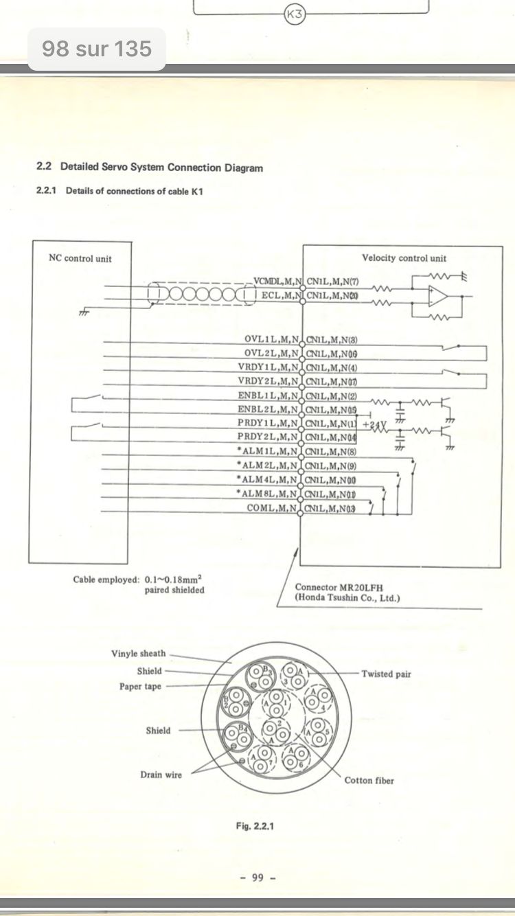
This is the shematic about the cable between the 7i77 and the PCB.
It's from this document : s3.amazonaws.com/Icarus/DOCUMENTS/Fanuc_Manuals_1785.pdf
It's from this document : s3.amazonaws.com/Icarus/DOCUMENTS/Fanuc_Manuals_1785.pdf
Please Log in or Create an account to join the conversation.
- andypugh
-

- Offline
- Moderator
-

Less
More
- Posts: 19770
- Thank you received: 4600
17 Aug 2017 15:56 #97649
by andypugh
Replied by andypugh on topic Fanuc and 5i25/7i77 couple
OK, so OVL, VRDY are dry-contact relay outputs, and ALM1, ALM2, ALM4 and ALM8 appear to send various alarm codes in a binary format.
It looks like you can probably just hard-wire PRDY1 to PRDY2.
It looks like you can probably just hard-wire PRDY1 to PRDY2.
The following user(s) said Thank You: ligthmare
Please Log in or Create an account to join the conversation.
- ligthmare
- Offline
- New Member
-

Less
More
- Posts: 16
- Thank you received: 0
17 Aug 2017 16:02 #97652
by ligthmare
Replied by ligthmare on topic Fanuc and 5i25/7i77 couple
I have been try hard-wire prdy1 and2 so since the shematic i must have 24v on Prdy1? it's not what happens , I hva no volatge on prdy1 or 2.
I think my pcb is failure.
I think my pcb is failure.
Please Log in or Create an account to join the conversation.
- andypugh
-

- Offline
- Moderator
-

Less
More
- Posts: 19770
- Thank you received: 4600
17 Aug 2017 21:15 #97671
by andypugh
Replied by andypugh on topic Fanuc and 5i25/7i77 couple
It shows 24V on PRDY2 and ENBL2
However, there isn't any exposed GND reference on any of the pins, so the voltage might be hard to measure.
Note that the enable output on the 7i77 is polarity-sensitive, so you would need to connect ENBL2 to the +ve side for it to work.
However, there isn't any exposed GND reference on any of the pins, so the voltage might be hard to measure.
Note that the enable output on the 7i77 is polarity-sensitive, so you would need to connect ENBL2 to the +ve side for it to work.
Please Log in or Create an account to join the conversation.
- ligthmare
- Offline
- New Member
-

Less
More
- Posts: 16
- Thank you received: 0
19 Aug 2017 19:40 #97752
by ligthmare
Replied by ligthmare on topic Fanuc and 5i25/7i77 couple
Thanks you it's works!! the probleme was from 2 wire in a cable for the X axis.
My motor move!!
But...during testing , one moto arrived on the end of the way and I have broken some transistor on the PCB I must to replace there . I have not 16000000 puls/rev but 2500 I was wrong . Its very complicated to mesure how many pulse I need to put in the case in the PNCconf for finaly have a correct scale. (I can't see inside the machine to see the leadsrew and pulley)
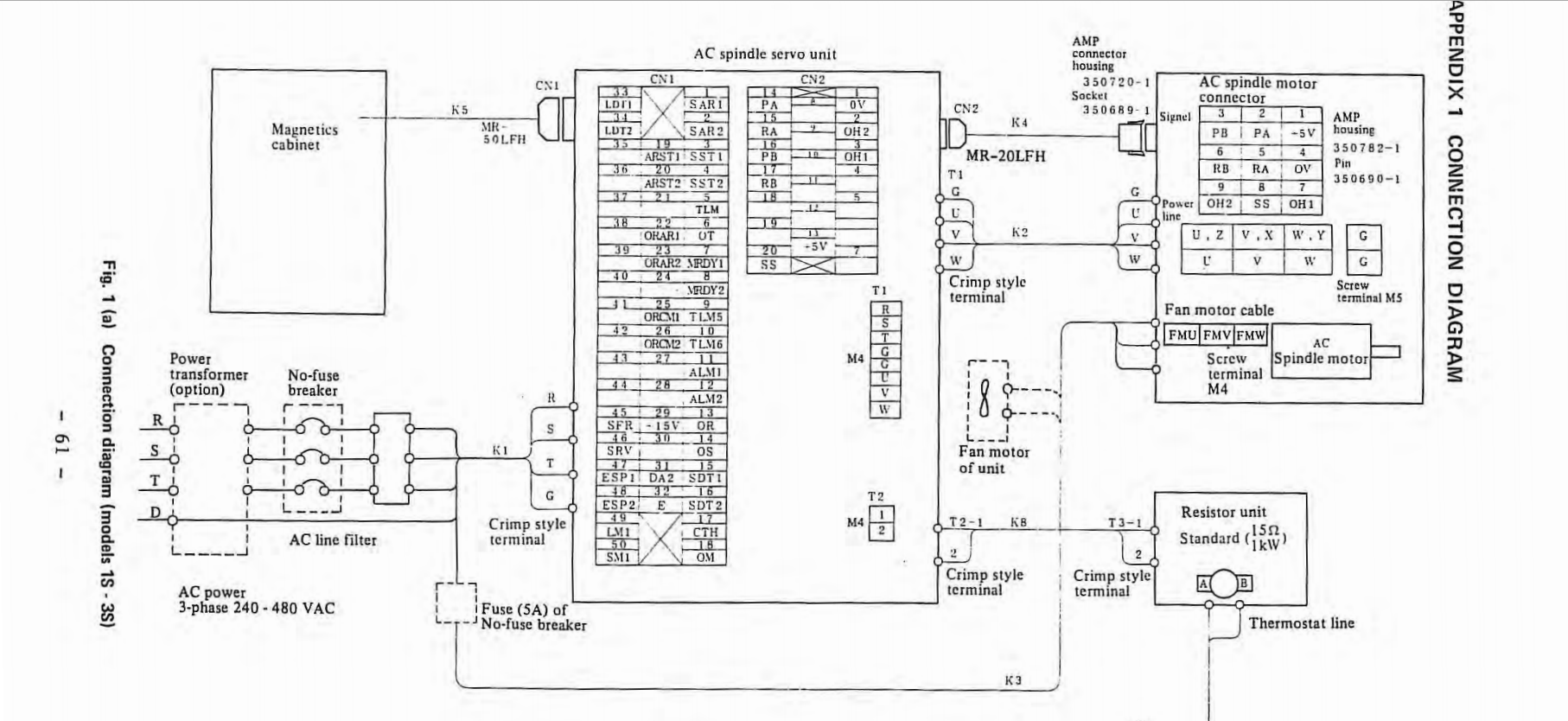
So, waiting the new transistor , I'm cheking about the spindle, and for taht I'm totaly lost.. On the 7i77 I have only 4 wire to drive the spindle ? the same as the axis?
Because on the cable ( CN1) between the 7i77 and the PCB its seems have a lot of information , and I do not understand the documetation.
What is the magnetic cabinet?
the documention , my unit is : a06b-6059-h002 cncmanual.com/fanuc-ac-spindle-servo-uni...nce-manual-65015e-2/
Please Log in or Create an account to join the conversation.
Moderators: PCW, jmelson
Time to create page: 0.102 seconds


