Easydriver how to get it to work?
- Marcodi
- Offline
- Elite Member
-

Less
More
- Posts: 198
- Thank you received: 13
05 Oct 2017 15:38 #99966
by Marcodi
Replied by Marcodi on topic Easydriver how to get it to work?
hi,
I took the same measurements with Saleae logic analyzer.
So when i make a run in the test box. I get following results. Channel 2 is my step dir. On one pictures you see there the drop in voltage.
I am just wondering if the voltage pulses are strong enough to be measured by the drivers.
Please any advice if this is sufficient would be helpful. Can i use direct parallel port or do i need a breakout board to enhance the pulses?
Please Log in or Create an account to join the conversation.
- Ozzyrob
-

- Visitor
-

05 Oct 2017 22:02 #99971
by Ozzyrob
Replied by Ozzyrob on topic Easydriver how to get it to work?
A buffered breakout board has been previously mentioned as well as configuring the parallel port for single direction rather than bi direction. A breakout board purchased from a specialist supplier will provide information on connecting their boards up. Usually drawing drawing more than 2.5ma from a PP pin will cause issues.
Pictures are not as useful as a schematic.
It gets frustrating to repeat advice that has already been given.
Pictures are not as useful as a schematic.
It gets frustrating to repeat advice that has already been given.
Please Log in or Create an account to join the conversation.
- Marcodi
- Offline
- Elite Member
-
Less
More
- Posts: 198
- Thank you received: 13
05 Oct 2017 22:16 #99972
by Marcodi
Replied by Marcodi on topic Easydriver how to get it to work?
Hi ozzyrob,
Ok, I get your point you don't want to repeat yourself, I am sorry for that.
The pictures I showed are the results from a logic analyzer on my own PP.
I have a breakout board coming in tomorrow, aswell as tb6600 drivers I will connect to that and see what happens.
My Mesa cards got in today but I don't want to use them yet till I fully understand and can make the PP work.
(Plus I just fried the motherboard on the computer I was gonna use. Spilled water of the watercooling on the rams. Fireworks...") ) Was a fun day this way.
) Was a fun day this way.
Ok, I get your point you don't want to repeat yourself, I am sorry for that.
The pictures I showed are the results from a logic analyzer on my own PP.
I have a breakout board coming in tomorrow, aswell as tb6600 drivers I will connect to that and see what happens.
My Mesa cards got in today but I don't want to use them yet till I fully understand and can make the PP work.
(Plus I just fried the motherboard on the computer I was gonna use. Spilled water of the watercooling on the rams. Fireworks...
) Was a fun day this way. Please Log in or Create an account to join the conversation.
- andypugh
-

- Offline
- Moderator
-

Less
More
- Posts: 19863
- Thank you received: 4636
05 Oct 2017 23:14 #99974
by andypugh
Replied by andypugh on topic Easydriver how to get it to work?
Many p-ports are 3.3V but 5V safe. The way to use them is in current-sinking mode. (also most can sing 15mA but might only source 3mA per pin).
The inputs to most stepper drivers are now opto-isolators, so you wire the +ve of the input opto to +5V (often from the PC USB socket) and then wire the -ve side of the opto to the parport.
You then need to inver the sense of the p-port pin in HAL so that 0V ( = current flow from 5V through opto to parport to gnd) is Step and 3,3V (= high impedance, no current flow) = space.
The following user(s) said Thank You: Marcodi
Please Log in or Create an account to join the conversation.
- Marcodi
- Offline
- Elite Member
-
Less
More
- Posts: 198
- Thank you received: 13
05 Oct 2017 23:25 #99975
by Marcodi
Replied by Marcodi on topic Easydriver how to get it to work?
Tomorrow I will upload a schematic of tb6600 and the settings in stepconfig. See if I get it right.
If it is correct, here on the forum might be great if people would have a subsection where you can upload a wiring schematic for a specific driver and settings that work. It would make a lot of questions unnecessary. (For future reference than). It's just an idea.
If it is correct, here on the forum might be great if people would have a subsection where you can upload a wiring schematic for a specific driver and settings that work. It would make a lot of questions unnecessary. (For future reference than). It's just an idea.
Please Log in or Create an account to join the conversation.
- Marcodi
- Offline
- Elite Member
-
Less
More
- Posts: 198
- Thank you received: 13
06 Oct 2017 09:53 - 06 Oct 2017 11:04 #99983
by Marcodi
Replied by Marcodi on topic Easydriver how to get it to work?
HI Everyone,
I made a schematic of the connection of TB6600 to the Parallel Port. I hope it is correct. If not, please let me know, i will change it accordingly. And hopefully the next person can use it aswell. I used pictures to make it as noob prove as possible, cause i would like to get it the same way, with my limited knowledge of electronics.
EDIT: updated the schematic, if someone with the knowledge could check it, so i don't distribute wrong schematics
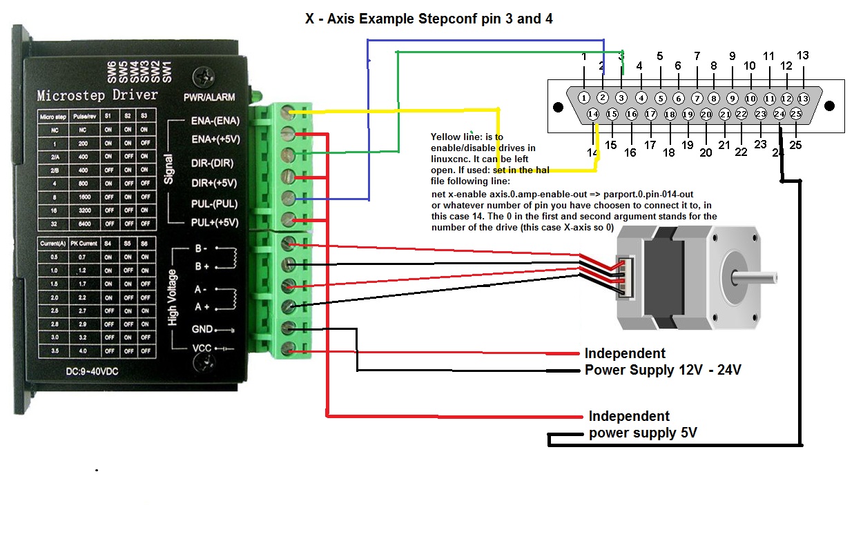
Regards,
Stephane
I made a schematic of the connection of TB6600 to the Parallel Port. I hope it is correct. If not, please let me know, i will change it accordingly. And hopefully the next person can use it aswell. I used pictures to make it as noob prove as possible, cause i would like to get it the same way, with my limited knowledge of electronics.
EDIT: updated the schematic, if someone with the knowledge could check it, so i don't distribute wrong schematics
Regards,
Stephane
Last edit: 06 Oct 2017 11:04 by Marcodi. Reason: updated schematic for review
Please Log in or Create an account to join the conversation.
- andypugh
-
- Offline
- Moderator
-
Less
More
- Posts: 19863
- Thank you received: 4636
06 Oct 2017 10:01 #99984
by andypugh
Replied by andypugh on topic Easydriver how to get it to work?
Your 5V supply should not be "independent" in that it must share a common 0V reference with the parallel port. If you use 5V from the PC PSU (conveniently available on the USB sockets) then this happens automatically. If you use a separate 5V then you can connect the PSU 0V to one or more of the parport GND pins.
On many drives the "enable" is a "disable" and can be left unconnected. If you want to disable the drives from LinuxCNC then you would connect the hal pin axis.N.amp-enable-out to a parallel port pin and use that.
On many drives the "enable" is a "disable" and can be left unconnected. If you want to disable the drives from LinuxCNC then you would connect the hal pin axis.N.amp-enable-out to a parallel port pin and use that.
The following user(s) said Thank You: Marcodi
Please Log in or Create an account to join the conversation.
- Marcodi
- Offline
- Elite Member
-
Less
More
- Posts: 198
- Thank you received: 13
06 Oct 2017 10:42 #99986
by Marcodi
Replied by Marcodi on topic Easydriver how to get it to work?
HI andypugh,
could you check if the schematic is correct now? Thanks.
could you check if the schematic is correct now? Thanks.
Please Log in or Create an account to join the conversation.
- andypugh
-
- Offline
- Moderator
-
Less
More
- Posts: 19863
- Thank you received: 4636
06 Oct 2017 10:48 #99989
by andypugh
Replied by andypugh on topic Easydriver how to get it to work?
Not quite, the N in axis.N refers to the axis number of the drive.
You need a HAL line like:
net x-enable axis.0.amp-enable-out => parport.0.pin-013-out
You need a HAL line like:
net x-enable axis.0.amp-enable-out => parport.0.pin-013-out
The following user(s) said Thank You: Marcodi
Please Log in or Create an account to join the conversation.
- Marcodi
- Offline
- Elite Member
-
Less
More
- Posts: 198
- Thank you received: 13
06 Oct 2017 11:05 #99990
by Marcodi
Replied by Marcodi on topic Easydriver how to get it to work?
hi,
I updated again, i hope now it has the perfect information for me and the next person
I updated again, i hope now it has the perfect information for me and the next person
Please Log in or Create an account to join the conversation.
Moderators: PCW, jmelson
Time to create page: 0.149 seconds