Help with 7i76 spindle direction control Please!
- Lcvette
-
 Topic Author
- Offline
- Platinum Member
-

Less
More
- Posts: 1630
- Thank you received: 760
27 Mar 2018 15:35 - 27 Mar 2018 15:37 #107958
by Lcvette
Help with 7i76 spindle direction control Please! was created by Lcvette
Hey guys,
I am finalizing my new schematic after deciding to just use the 7i92m and 7i76 and not use the 7i77 anymore but it has generated a few questions i'm not certain how to answer. I searched online and have seen a few different methods for controling spindle direction and I think i understand this a little bit but not enough to risk running wires and turning power on with expensive equipment. I have added some information in the form of my schematic for the machine build i have along with 3 pages from the manual for my spindle servo drive which isn't terribly useful for someone like me who is at a spoonfed requirement level. I was hoping some of the more experienced people in here coule help shine some light and understanding on how to properly get the spindle direction control wired with my configuration.
please see the below information, In the pdf schematic I have highlighted the connection points I am uncertain about in yellow, they are mid schematic on the left side on the spindle drive block.
Thank you all in advance for taking the time to look!


Thanks!
I am finalizing my new schematic after deciding to just use the 7i92m and 7i76 and not use the 7i77 anymore but it has generated a few questions i'm not certain how to answer. I searched online and have seen a few different methods for controling spindle direction and I think i understand this a little bit but not enough to risk running wires and turning power on with expensive equipment. I have added some information in the form of my schematic for the machine build i have along with 3 pages from the manual for my spindle servo drive which isn't terribly useful for someone like me who is at a spoonfed requirement level. I was hoping some of the more experienced people in here coule help shine some light and understanding on how to properly get the spindle direction control wired with my configuration.
please see the below information, In the pdf schematic I have highlighted the connection points I am uncertain about in yellow, they are mid schematic on the left side on the spindle drive block.
Thank you all in advance for taking the time to look!
Thanks!
Last edit: 27 Mar 2018 15:37 by Lcvette.
Please Log in or Create an account to join the conversation.
- andypugh
-

- Offline
- Moderator
-

Less
More
- Posts: 19875
- Thank you received: 4641
27 Mar 2018 16:20 #107959
by andypugh
Replied by andypugh on topic Help with 7i76 spindle direction control Please!
That's quite an interesting drive, offering lots of possible ways to control it.
It looks like you could control it using step-dir outputs from the 7i76 if that was convenient.
But for analogue 0-10V control:
7i76 TB4 -> Spindle Connector
1 (spindle - ) -> 29 (GND)
2 (spindle out) -> 15 (A1)
3 (spindle +) -> 30 (12V)
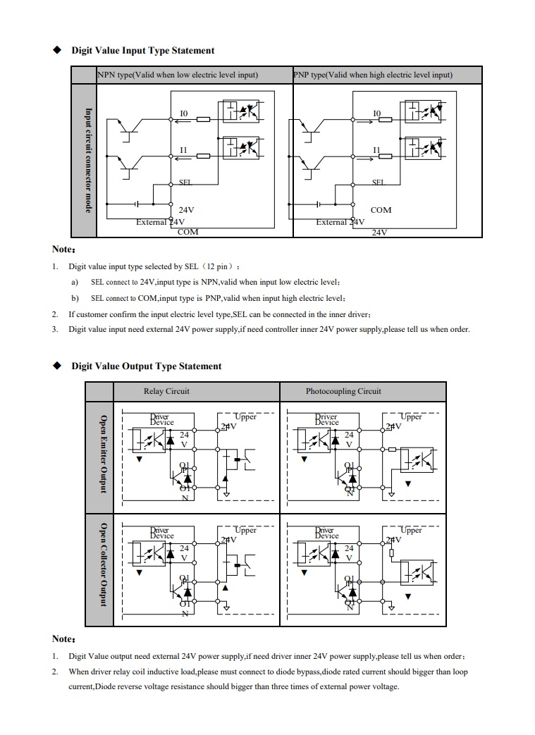
But the digital input diagrams are a bit confusing.
I think you can connect SEL (pin 12) to 24V field power, then:
5 (Spindle ENA -) -> Field power gnd
6 (Spindle ENA + ) -> CW (10? 22?)
Can you explain whether the 44 pin connector is the only connection for control / FB, or does it duplicate screw terminals? I thought I was clear until I noticed that the table says "terminal 10 is pin 22"
It looks like you could control it using step-dir outputs from the 7i76 if that was convenient.
But for analogue 0-10V control:
7i76 TB4 -> Spindle Connector
1 (spindle - ) -> 29 (GND)
2 (spindle out) -> 15 (A1)
3 (spindle +) -> 30 (12V)
But the digital input diagrams are a bit confusing.
I think you can connect SEL (pin 12) to 24V field power, then:
5 (Spindle ENA -) -> Field power gnd
6 (Spindle ENA + ) -> CW (10? 22?)
Can you explain whether the 44 pin connector is the only connection for control / FB, or does it duplicate screw terminals? I thought I was clear until I noticed that the table says "terminal 10 is pin 22"
The following user(s) said Thank You: Lcvette
Please Log in or Create an account to join the conversation.
- PCW
-

- Offline
- Moderator
-
Less
More
- Posts: 17954
- Thank you received: 5261
27 Mar 2018 16:21 #107960
by PCW
Replied by PCW on topic Help with 7i76 spindle direction control Please!
If the direction inputs can only be programmed as CW/CCW, its probably easiest to drive the CW/CCW pins from field outputs (using the "PNP type" input wiring)
That is SEL pin to field voltage (24V) common
That is SEL pin to field voltage (24V) common
The following user(s) said Thank You: Lcvette
Please Log in or Create an account to join the conversation.
- Lcvette
-
Topic Author
- Offline
- Platinum Member
-
Less
More
- Posts: 1630
- Thank you received: 760
27 Mar 2018 16:37 #107968
by Lcvette
yes very confusing.... and it requires an external power supply (or if requested ahead of time one can be supplied built in, but I was unaware of course at time of purchase).. I am attaching the full PDF manual below. I believe there are some internal settings that allow the default direction of rotation to be set with some additional conditions, but that started to confuse me even further.. if you have a moment to check the manual it is rather short, usually i get bogged down in big manual but in this case, it leaves alot to be desired. but perhaps my amateur hour eyes are missing a key piece of information...?
Replied by Lcvette on topic Help with 7i76 spindle direction control Please!
That's quite an interesting drive, offering lots of possible ways to control it.
It looks like you could control it using step-dir outputs from the 7i76 if that was convenient.
But for analogue 0-10V control:
7i76 TB4 -> Spindle Connector
1 (spindle - ) -> 29 (GND)
2 (spindle out) -> 15 (A1)
3 (spindle +) -> 30 (12V)
But the digital input diagrams are a bit confusing.
I think you can connect SEL (pin 12) to 24V field power, then:
5 (Spindle ENA -) -> Field power gnd
6 (Spindle ENA + ) -> CW (10? 22?)
Can you explain whether the 44 pin connector is the only connection for control / FB, or does it duplicate screw terminals? I thought I was clear until I noticed that the table says "terminal 10 is pin 22"
yes very confusing.... and it requires an external power supply (or if requested ahead of time one can be supplied built in, but I was unaware of course at time of purchase).. I am attaching the full PDF manual below. I believe there are some internal settings that allow the default direction of rotation to be set with some additional conditions, but that started to confuse me even further.. if you have a moment to check the manual it is rather short, usually i get bogged down in big manual but in this case, it leaves alot to be desired. but perhaps my amateur hour eyes are missing a key piece of information...?
Please Log in or Create an account to join the conversation.
- Lcvette
-
Topic Author
- Offline
- Platinum Member
-
Less
More
- Posts: 1630
- Thank you received: 760
27 Mar 2018 16:45 #107969
by Lcvette
hmmm, I had not considered that option Peter, just using to regular outputs programmed to run forward and reverse.... I would hate to lose those as im starting to get low on outputs and have a few other items i would like to add in in the near future once everything is up and running. but I suppose as a last resort that would work.
Chris
Replied by Lcvette on topic Help with 7i76 spindle direction control Please!
If the direction inputs can only be programmed as CW/CCW, its probably easiest to drive the CW/CCW pins from field outputs (using the "PNP type" input wiring)
That is SEL pin to field voltage (24V) common
hmmm, I had not considered that option Peter, just using to regular outputs programmed to run forward and reverse.... I would hate to lose those as im starting to get low on outputs and have a few other items i would like to add in in the near future once everything is up and running. but I suppose as a last resort that would work.
Chris
Please Log in or Create an account to join the conversation.
- andypugh
-
- Offline
- Moderator
-
Less
More
- Posts: 19875
- Thank you received: 4641
27 Mar 2018 17:07 #107973
by andypugh
Replied by andypugh on topic Help with 7i76 spindle direction control Please!
Do you need reverse?
The 7i76 outputs suit ON / REV drives rather better than FWD / REV drives. Can your drive be configured that way?
The 7i76 outputs suit ON / REV drives rather better than FWD / REV drives. Can your drive be configured that way?
Please Log in or Create an account to join the conversation.
- Lcvette
-
Topic Author
- Offline
- Platinum Member
-
Less
More
- Posts: 1630
- Thank you received: 760
27 Mar 2018 17:08 #107974
by Lcvette
terminal 10 is actually i0 and its pin 22 in a 44pin connector plug CN3. I added the labeling they had incase it was relevant during programming for some reason at a later date.
as for using a p[ulse configuration, I would prefer not to as I have plans to quickly add in a trunnion table 4th and 5th on this machine and hope to be able to remain using just the 7i76 board for everything to keep things simple. I agree it is confusing.
there is a table in the manual for spindle direction programming but it further confuses me in how it is written. I am not sure if it is because im just not getting it and I should or if it is simply written depicted poorly. either is very possible...
Replied by Lcvette on topic Help with 7i76 spindle direction control Please!
That's quite an interesting drive, offering lots of possible ways to control it.
It looks like you could control it using step-dir outputs from the 7i76 if that was convenient.
But for analogue 0-10V control:
7i76 TB4 -> Spindle Connector
1 (spindle - ) -> 29 (GND)
2 (spindle out) -> 15 (A1)
3 (spindle +) -> 30 (12V)
But the digital input diagrams are a bit confusing.
I think you can connect SEL (pin 12) to 24V field power, then:
5 (Spindle ENA -) -> Field power gnd
6 (Spindle ENA + ) -> CW (10? 22?)
Can you explain whether the 44 pin connector is the only connection for control / FB, or does it duplicate screw terminals? I thought I was clear until I noticed that the table says "terminal 10 is pin 22"
terminal 10 is actually i0 and its pin 22 in a 44pin connector plug CN3. I added the labeling they had incase it was relevant during programming for some reason at a later date.
as for using a p[ulse configuration, I would prefer not to as I have plans to quickly add in a trunnion table 4th and 5th on this machine and hope to be able to remain using just the 7i76 board for everything to keep things simple. I agree it is confusing.
there is a table in the manual for spindle direction programming but it further confuses me in how it is written. I am not sure if it is because im just not getting it and I should or if it is simply written depicted poorly. either is very possible...
Please Log in or Create an account to join the conversation.
- Lcvette
-
Topic Author
- Offline
- Platinum Member
-
Less
More
- Posts: 1630
- Thank you received: 760
27 Mar 2018 17:18 #107975
by Lcvette
Yes, definitely need reverse for rigid tapping, this is a vmc sized machine retrofit..

Replied by Lcvette on topic Help with 7i76 spindle direction control Please!
Do you need reverse?
The 7i76 outputs suit ON / REV drives rather better than FWD / REV drives. Can your drive be configured that way?
Yes, definitely need reverse for rigid tapping, this is a vmc sized machine retrofit..
Please Log in or Create an account to join the conversation.
- andypugh
-
- Offline
- Moderator
-
Less
More
- Posts: 19875
- Thank you received: 4641
27 Mar 2018 17:19 #107977
by andypugh
Replied by andypugh on topic Help with 7i76 spindle direction control Please!
It says that if you have FWD and REV at the same time then you get REV, so that's fine. You can wire FWD to 7i76-On and REV to 7i76-Rev as long as you set E41 and E42 both to zero.
The following user(s) said Thank You: Lcvette
Please Log in or Create an account to join the conversation.
- andypugh
-
- Offline
- Moderator
-
Less
More
- Posts: 19875
- Thank you received: 4641
27 Mar 2018 17:20 #107978
by andypugh
Replied by andypugh on topic Help with 7i76 spindle direction control Please!
The drive has special inputs for rigid tapping. You ought to be able to drive that from HAL by looking at motion.motion-type
The following user(s) said Thank You: Lcvette
Please Log in or Create an account to join the conversation.
Moderators: PCW, jmelson
Time to create page: 0.233 seconds