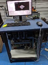
Wiring a Chinese servo to a 7i77. Setup for yet another newbie
- bevins
-

- Offline
- Platinum Member
-

Less
More
- Posts: 1942
- Thank you received: 338
15 Oct 2019 20:21 #147943
by bevins
Why are you not connecting the index of the encoders?
Replied by bevins on topic Wiring a Chinese servo to a 7i77. Setup for yet another newbie
\
Also +-10V from Mesa to pin 25 and 13 respectively .TB3 PIN FUNCTION DIR
1 QA0 TO 7I77 PA+ pin 20
2 /QA0 TO 7I77 PA- pin19
3 GND FROM 7I77 GND pin 1
4 QB0 TO 7I77 PB+ pin 18
5 /QB0 TO 7I77 PB- pin 17
6 +5V FROM 7I77 do not connect
7 IDX0 TO 7I77 do not connect
8 /IDX0 TO 7I77 do not connect
Drive enable from Mesa to pin 29 and 9.
Why are you not connecting the index of the encoders?
Please Log in or Create an account to join the conversation.
- SPH
-
 Topic Author
- Offline
- Premium Member
-

Less
More
- Posts: 109
- Thank you received: 6
15 Oct 2019 20:35 #147946
by SPH
Replied by SPH on topic Wiring a Chinese servo to a 7i77. Setup for yet another newbie
Let me know how the index connects and I’ll wire it in. Perhaps tommylight’s directions were just the basics?
The drive enable is so obvious now, thanks. Don’t know what was thinking.
The drive enable is so obvious now, thanks. Don’t know what was thinking.
Please Log in or Create an account to join the conversation.
- tommylight
-

- Away
- Moderator
-

Less
More
- Posts: 21157
- Thank you received: 7224
15 Oct 2019 21:11 #147947
by tommylight
Replied by tommylight on topic Wiring a Chinese servo to a 7i77. Setup for yet another newbie
Just checked it again, did not notice that there is a normal output for Z (index) AND an open collector output, saw only open collector that evening, sorry my bad. Anyway i was trying to make it simple for him, due to open collector requiring resistors to be added and different wiring needs.
Back to it, the Z or index pins are 15 for enc+ and 16 for enc-.
Back to it, the Z or index pins are 15 for enc+ and 16 for enc-.
Please Log in or Create an account to join the conversation.
- bevins
-

- Offline
- Platinum Member
-

Less
More
- Posts: 1942
- Thank you received: 338
16 Oct 2019 00:31 #147961
by bevins
How did you wire the enable pins?
Also make sure you have the correct motor selected in the programming. I am still looking for my parameter sheet. It is in a backup and I haven't located it yet.
Replied by bevins on topic Wiring a Chinese servo to a 7i77. Setup for yet another newbie
Let me know how the index connects and I’ll wire it in. Perhaps tommylight’s directions were just the basics?
The drive enable is so obvious now, thanks. Don’t know what was thinking.
How did you wire the enable pins?
Also make sure you have the correct motor selected in the programming. I am still looking for my parameter sheet. It is in a backup and I haven't located it yet.
Please Log in or Create an account to join the conversation.
- SPH
-
 Topic Author
- Offline
- Premium Member
-

Less
More
- Posts: 109
- Thank you received: 6
17 Oct 2019 01:05 #148068
by SPH
Replied by SPH on topic Wiring a Chinese servo to a 7i77. Setup for yet another newbie
I haven't wired the enable yet, still trying to get some idea how its supposed to work using a DMM. It looks like I should be sending pin 9 which is the positive supply from the drive to ENAN+ on the 7i77 and then ENAN- to pin 6 on the drive which is SRVON.
I assumed I'd be able to pick up a 12 or 24v signal from the drive though between pin 9 and ground but so far no luck so I'm still a bit lost as to what's going on.
I assumed I'd be able to pick up a 12 or 24v signal from the drive though between pin 9 and ground but so far no luck so I'm still a bit lost as to what's going on.
Please Log in or Create an account to join the conversation.
- PCW
-

- Offline
- Moderator
-

Less
More
- Posts: 17577
- Thank you received: 5141
17 Oct 2019 03:18 #148069
by PCW
Replied by PCW on topic Wiring a Chinese servo to a 7i77. Setup for yet another newbie
The 7I77 drive enable pins (ENAN+ and ENAN-) are just a floating switch
Its usually a good idea to verify that you can enable /disable
the drive with a mechanical switch before wiring to the 7I77
Its usually a good idea to verify that you can enable /disable
the drive with a mechanical switch before wiring to the 7I77
Please Log in or Create an account to join the conversation.
- SPH
-
 Topic Author
- Offline
- Premium Member
-

Less
More
- Posts: 109
- Thank you received: 6
17 Oct 2019 05:37 #148071
by SPH
Replied by SPH on topic Wiring a Chinese servo to a 7i77. Setup for yet another newbie
Thats what I figured too. I thought I should be able to just bridge pins 6 and 9 on the drive and get it to enable. I'm away for a few days so I'll dig back into it when I get home
Please Log in or Create an account to join the conversation.
- bevins
-

- Offline
- Platinum Member
-

Less
More
- Posts: 1942
- Thank you received: 338
17 Oct 2019 07:56 - 17 Oct 2019 07:57 #148090
by bevins
Replied by bevins on topic Wiring a Chinese servo to a 7i77. Setup for yet another newbie
What I do is connect outputs to machine-is-on. That way relays get energized and I use the contacts to enable the drives, Its easy to blow those outputs, just ask me how I know. This way it is bullet proof.
Last edit: 17 Oct 2019 07:57 by bevins.
Please Log in or Create an account to join the conversation.
- SPH
-
 Topic Author
- Offline
- Premium Member
-

Less
More
- Posts: 109
- Thank you received: 6
20 Oct 2019 09:34 #148393
by SPH
Replied by SPH on topic Wiring a Chinese servo to a 7i77. Setup for yet another newbie
I sorted it out. Nothing too complicated as usual, in hindsight.
The drive needs external +24v power for it's inputs, DC+ on pin 9 and DC- switched on pin 6 for enable.
External 24v+ to TB5 pin 2, 24v+ switched from TB5 pin 1 to pin 6 on the drive. 24- to pin 6 on the drive.
Enable now works and soft estop also works as expected. I'll get a hard estop working next.
There's about 1/8 of a shaft rotation just as the drive enables. Perhaps something to do with the fairly high rpm drift when the loop isn't closed? Should I be chasing drive parameters to tone this down or is it something in software? I imagine it'll make for a pretty good mechanical 'clunk' when everything connected for real.
Please Log in or Create an account to join the conversation.
- SPH
-
 Topic Author
- Offline
- Premium Member
-

Less
More
- Posts: 109
- Thank you received: 6
22 Oct 2019 06:26 #148528
by SPH
Replied by SPH on topic Wiring a Chinese servo to a 7i77. Setup for yet another newbie
I've got the X and Z axis' wired and running. Jogging is acceptable.
I take it the tuning will be influenced by the actual mechanics of the machine so I shouldn't get too far into the tuning until the servos are actually mounted?
I'll also have the fun job of re-wiring my encoder and motor plugs as I somewhat foolishly decided to use the existing motor cables from the Yaskawas to save a buck. Should'a just spend the buck. The motor cables are easy of course, just the 4 wires. It's the 15 pin encoder cables I'm not too keen on.
Please Log in or Create an account to join the conversation.
Moderators: PCW, jmelson
Time to create page: 0.090 seconds
