7i80hd + 7i33 + 7i37 + 7i84
- vre
- Offline
- Platinum Member
-

- Posts: 610
- Thank you received: 17
I have installed xilinx ise 14.7 and i want a PIN file for 7i80hd + 7i33 + 7i37 + 7i84
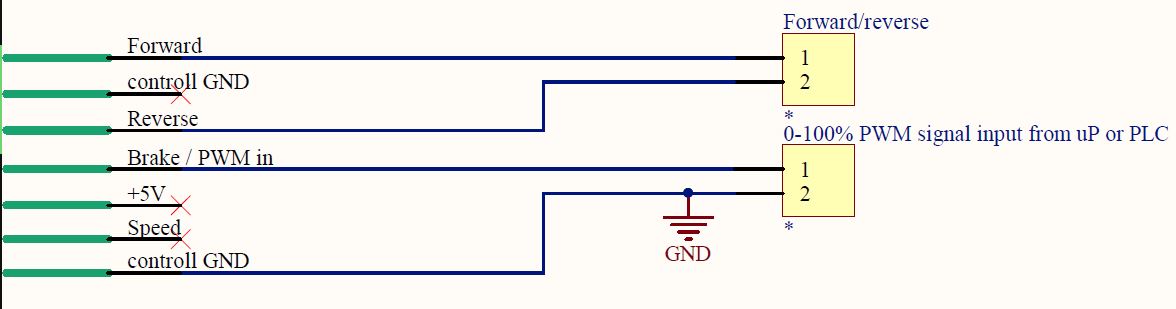
For 7i33 the pwm output must be like this in the photo because dc motor driver accepts that type of pwm
My problem is that i want 2 outputs for direction forward & reverse not only 1 direction.
Also for connecting 7i84 to 7i80hd i have this adapter www.aliexpress.com/item/4000542156362.html
Can someone help me with pin file ?
I have this pin file but does not outputs the forward-reverse signals in the form shown in the photo
library IEEE;
use IEEE.std_logic_1164.all;  -- defines std_logic types
use IEEE.STD_LOGIC_ARITH.ALL;
use IEEE.STD_LOGIC_UNSIGNED.ALL;

-- Copyright (C) 2007, Peter C. Wallace, Mesa Electronics
-- http://www.mesanet.com
--
-- This program is is licensed under a disjunctive dual license giving you
-- the choice of one of the two following sets of free software/open source
-- licensing terms:
--
--    * GNU General Public License (GPL), version 2.0 or later
--    * 3-clause BSD License
--
--
-- The GNU GPL License:
--
--     This program is free software; you can redistribute it and/or modify
--     it under the terms of the GNU General Public License as published by
--     the Free Software Foundation; either version 2 of the License, or
--     (at your option) any later version.
--
--     This program is distributed in the hope that it will be useful,
--     but WITHOUT ANY WARRANTY; without even the implied warranty of
--     MERCHANTABILITY or FITNESS FOR A PARTICULAR PURPOSE.  See the
--     GNU General Public License for more details.
--
--     You should have received a copy of the GNU General Public License
--     along with this program; if not, write to the Free Software
--     Foundation, Inc., 51 Franklin St, Fifth Floor, Boston, MA  02110-1301 USA
--
--
-- The 3-clause BSD License:
--
--     Redistribution and use in source and binary forms, with or without
--     modification, are permitted provided that the following conditions
--     are met:
--
--   * Redistributions of source code must retain the above copyright
--     notice, this list of conditions and the following disclaimer.
--
--   * Redistributions in binary form must reproduce the above
--     copyright notice, this list of conditions and the following
--     disclaimer in the documentation and/or other materials
--     provided with the distribution.
--
--   * Neither the name of Mesa Electronics nor the names of its
--     contributors may be used to endorse or promote products
--     derived from this software without specific prior written
--     permission.
--
--
-- Disclaimer:
--
--     THIS SOFTWARE IS PROVIDED BY THE COPYRIGHT HOLDERS AND CONTRIBUTORS
--     "AS IS" AND ANY EXPRESS OR IMPLIED WARRANTIES, INCLUDING, BUT NOT
--     LIMITED TO, THE IMPLIED WARRANTIES OF MERCHANTABILITY AND FITNESS
--     FOR A PARTICULAR PURPOSE ARE DISCLAIMED. IN NO EVENT SHALL THE
--     COPYRIGHT OWNER OR CONTRIBUTORS BE LIABLE FOR ANY DIRECT, INDIRECT,
--     INCIDENTAL, SPECIAL, EXEMPLARY, OR CONSEQUENTIAL DAMAGES (INCLUDING,
--     BUT NOT LIMITED TO, PROCUREMENT OF SUBSTITUTE GOODS OR SERVICES;
--     LOSS OF USE, DATA, OR PROFITS; OR BUSINESS INTERRUPTION) HOWEVER
--     CAUSED AND ON ANY THEORY OF LIABILITY, WHETHER IN CONTRACT, STRICT
--     LIABILITY, OR TORT (INCLUDING NEGLIGENCE OR OTHERWISE) ARISING IN
--     ANY WAY OUT OF THE USE OF THIS SOFTWARE, EVEN IF ADVISED OF THE
--     POSSIBILITY OF SUCH DAMAGE.
--

use work.IDROMConst.all;

package PIN_SV4_7I33_SSERIAL_72 is
    constant ModuleID : ModuleIDType :=(
        (WatchDogTag,        x"00",    ClockLowTag,            x"01",    WatchDogTimeAddr&PadT,                WatchDogNumRegs,            x"00",    WatchDogMPBitMask),
        (IOPortTag,        x"00",    ClockLowTag,            x"03",    PortAddr&PadT,                    IOPortNumRegs,                x"00",    IOPortMPBitMask),
        (QcountTag,        x"02",    ClockLowTag,            x"08",    QcounterAddr&PadT,                QCounterNumRegs,            x"00",    QCounterMPBitMask),
        (PWMTag,        x"00",    ClockHighTag,            x"05",    PWMValAddr&PadT,                PWMNumRegs,                x"00",    PWMMPBitMask),
             (SSerialTag,        x"00",  ClockLowTag,                x"01",  SSerialCommandAddr&PadT,                   SSerialNumRegs,                 x"10",  SSerialMPBitMask),
        (LEDTag,        x"00",    ClockLowTag,            x"01",    LEDAddr&PadT,                    LEDNumRegs,                x"00",    LEDMPBitMask),
        (NullTag,        x"00",    NullTag,            x"00",    NullAddr&PadT,                    x"00",                    x"00",    x"00000000"),
        (NullTag,        x"00",    NullTag,            x"00",    NullAddr&PadT,                    x"00",                    x"00",    x"00000000"),
        (NullTag,        x"00",    NullTag,            x"00",    NullAddr&PadT,                    x"00",                    x"00",    x"00000000"),
        (NullTag,        x"00",    NullTag,            x"00",    NullAddr&PadT,                    x"00",                    x"00",    x"00000000"),
        (NullTag,        x"00",    NullTag,            x"00",    NullAddr&PadT,                    x"00",                    x"00",    x"00000000"),
        (NullTag,        x"00",    NullTag,            x"00",    NullAddr&PadT,                    x"00",                    x"00",    x"00000000"),
        (NullTag,        x"00",    NullTag,            x"00",    NullAddr&PadT,                    x"00",                    x"00",    x"00000000"),
        (NullTag,        x"00",    NullTag,            x"00",    NullAddr&PadT,                    x"00",                    x"00",    x"00000000"),
        (NullTag,        x"00",    NullTag,            x"00",    NullAddr&PadT,                    x"00",                    x"00",    x"00000000"),
        (NullTag,        x"00",    NullTag,            x"00",    NullAddr&PadT,                    x"00",                    x"00",    x"00000000"),
        (NullTag,        x"00",    NullTag,            x"00",    NullAddr&PadT,                    x"00",                    x"00",    x"00000000"),
        (NullTag,        x"00",    NullTag,            x"00",    NullAddr&PadT,                    x"00",                    x"00",    x"00000000"),
        (NullTag,        x"00",    NullTag,            x"00",    NullAddr&PadT,                    x"00",                    x"00",    x"00000000"),
        (NullTag,        x"00",    NullTag,            x"00",    NullAddr&PadT,                    x"00",                    x"00",    x"00000000"),
        (NullTag,        x"00",    NullTag,            x"00",    NullAddr&PadT,                    x"00",                    x"00",    x"00000000"),
        (NullTag,        x"00",    NullTag,            x"00",    NullAddr&PadT,                    x"00",                    x"00",    x"00000000"),
        (NullTag,        x"00",    NullTag,            x"00",    NullAddr&PadT,                    x"00",                    x"00",    x"00000000"),
        (NullTag,        x"00",    NullTag,            x"00",    NullAddr&PadT,                    x"00",                    x"00",    x"00000000"),
        (NullTag,        x"00",    NullTag,            x"00",    NullAddr&PadT,                    x"00",                    x"00",    x"00000000"),
        (NullTag,        x"00",    NullTag,            x"00",    NullAddr&PadT,                    x"00",                    x"00",    x"00000000"),
        (NullTag,        x"00",    NullTag,            x"00",    NullAddr&PadT,                    x"00",                    x"00",    x"00000000"),
        (NullTag,        x"00",    NullTag,            x"00",    NullAddr&PadT,                    x"00",                    x"00",    x"00000000"),
        (NullTag,        x"00",    NullTag,            x"00",    NullAddr&PadT,                    x"00",                    x"00",    x"00000000"),
        (NullTag,        x"00",    NullTag,            x"00",    NullAddr&PadT,                    x"00",                    x"00",    x"00000000"),
        (NullTag,        x"00",    NullTag,            x"00",    NullAddr&PadT,                    x"00",                    x"00",    x"00000000"),
        (NullTag,        x"00",    NullTag,            x"00",    NullAddr&PadT,                    x"00",                    x"00",    x"00000000")
        );


    constant PinDesc : PinDescType :=(
--     Base func  sec unit sec func      sec pin
        IOPortTag & x"01" & QCountTag & x"02",                    -- I/O 00
        IOPortTag & x"01" & QCountTag & x"01",                   -- I/O 01
        IOPortTag & x"00" & QCountTag & x"02",                -- I/O 02
        IOPortTag & x"00" & QCountTag & x"01",                -- I/O 03
        IOPortTag & x"01" & QCountTag & x"03",                -- I/O 04
        IOPortTag & x"00" & QCountTag & x"03",                -- I/O 05
        IOPortTag & x"01" & PWMTag & x"81",                   -- I/O 06
        IOPortTag & x"00" & PWMTag & x"81",                   -- I/O 07
        IOPortTag & x"01" & PWMTag & x"82",                   -- I/O 08
        IOPortTag & x"00" & PWMTag & x"82",                   -- I/O 09
        IOPortTag & x"01" & PWMTag & x"83",                   -- I/O 10
        IOPortTag & x"00" & PWMTag & x"83",                   -- I/O 11
        IOPortTag & x"03" & QCountTag & x"02",                -- I/O 12
        IOPortTag & x"03" & QCountTag & x"01",                -- I/O 13
        IOPortTag & x"02" & QCountTag & x"02",                -- I/O 14
        IOPortTag & x"02" & QCountTag & x"01",                -- I/O 15
        IOPortTag & x"03" & QCountTag & x"03",                -- I/O 16
        IOPortTag & x"02" & QCountTag & x"03",                -- I/O 17
        IOPortTag & x"03" & PWMTag & x"81",                   -- I/O 18
        IOPortTag & x"02" & PWMTag & x"81",                   -- I/O 19
        IOPortTag & x"03" & PWMTag & x"82",                   -- I/O 20
        IOPortTag & x"02" & PWMTag & x"82",                   -- I/O 21
        IOPortTag & x"03" & PWMTag & x"83",                   -- I/O 22
        IOPortTag & x"02" & PWMTag & x"83",                   -- I/O 23


        IOPortTag & x"00" & NullTag & x"00",                               -- I/O 24
        IOPortTag & x"00" & NullTag & x"00",                               -- I/O 25
        IOPortTag & x"00" & NullTag & x"00",                               -- I/O 26
        IOPortTag & x"00" & NullTag & x"00",                               -- I/O 27
        IOPortTag & x"00" & NullTag & x"00",                               -- I/O 28
        IOPortTag & x"00" & NullTag & x"00",                               -- I/O 29
        IOPortTag & x"00" & NullTag & x"00",                               -- I/O 30
        IOPortTag & x"00" & NullTag & x"00",                               -- I/O 31
        IOPortTag & x"00" & NullTag & x"00",                               -- I/O 32
        IOPortTag & x"00" & NullTag & x"00",                               -- I/O 33
        IOPortTag & x"00" & NullTag & x"00",                               -- I/O 34
        IOPortTag & x"00" & NullTag & x"00",                               -- I/O 35
        IOPortTag & x"00" & NullTag & x"00",                               -- I/O 36
        IOPortTag & x"00" & NullTag & x"00",                               -- I/O 37
        IOPortTag & x"00" & NullTag & x"00",                               -- I/O 38
        IOPortTag & x"00" & NullTag & x"00",                               -- I/O 39
        IOPortTag & x"00" & NullTag & x"00",                               -- I/O 40
        IOPortTag & x"00" & NullTag & x"00",                               -- I/O 41
        IOPortTag & x"00" & NullTag & x"00",                               -- I/O 42
        IOPortTag & x"00" & NullTag & x"00",                               -- I/O 43
        IOPortTag & x"00" & NullTag & x"00",                               -- I/O 44
        IOPortTag & x"00" & NullTag & x"00",                               -- I/O 45
        IOPortTag & x"00" & NullTag & x"00",                               -- I/O 46
        IOPortTag & x"00" & NullTag & x"00",                               -- I/O 47


        IOPortTag & x"00" & SSerialTag & SSerialRX0Pin,         -- I/O 48
        IOPortTag & x"00" & SSerialTag & SSerialTX0Pin,         -- I/O 49
        IOPortTag & x"00" & SSerialTag & SSerialRX1Pin,         -- I/O 50
        IOPortTag & x"00" & SSerialTag & SSerialTX1Pin,         -- I/O 51
        IOPortTag & x"00" & SSerialTag & SSerialRX2Pin,         -- I/O 52
        IOPortTag & x"00" & SSerialTag & SSerialTX2Pin,         -- I/O 53
        IOPortTag & x"00" & SSerialTag & SSerialRX3Pin,         -- I/O 54
        IOPortTag & x"00" & SSerialTag & SSerialTX3Pin,         -- I/O 55
        IOPortTag & x"00" & SSerialTag & SSerialRX4Pin,         -- I/O 56
        IOPortTag & x"00" & SSerialTag & SSerialTX4Pin,         -- I/O 57
        IOPortTag & x"00" & SSerialTag & SSerialRX5Pin,         -- I/O 58
        IOPortTag & x"00" & SSerialTag & SSerialTX5Pin,         -- I/O 59
        IOPortTag & x"00" & NullTag & x"00",                    -- I/O 60
        IOPortTag & x"00" & NullTag & x"00",                    -- I/O 61
        IOPortTag & x"00" & NullTag & x"00",                    -- I/O 62
        IOPortTag & x"00" & NullTag & x"00",                    -- I/O 63
        IOPortTag & x"00" & NullTag & x"00",                    -- I/O 64
        IOPortTag & x"00" & NullTag & x"00",                    -- I/O 65
        IOPortTag & x"00" & NullTag & x"00",                    -- I/O 66
        IOPortTag & x"00" & NullTag & x"00",                    -- I/O 67
        IOPortTag & x"00" & NullTag & x"00",                    -- I/O 68
        IOPortTag & x"00" & NullTag & x"00",                    -- I/O 69
        IOPortTag & x"00" & NullTag & x"00",                    -- I/O 70
        IOPortTag & x"00" & NullTag & x"00",                    -- I/O 71

        emptypin,emptypin,emptypin,emptypin,emptypin,emptypin,emptypin,emptypin, -- added for IDROM v3
        emptypin,emptypin,emptypin,emptypin,emptypin,emptypin,emptypin,emptypin,

        emptypin,emptypin,emptypin,emptypin,emptypin,emptypin,emptypin,emptypin,
        emptypin,emptypin,emptypin,emptypin,emptypin,emptypin,emptypin,emptypin,
        emptypin,emptypin,emptypin,emptypin,emptypin,emptypin,emptypin,emptypin,
        emptypin,emptypin,emptypin,emptypin,emptypin,emptypin,emptypin,emptypin,
        emptypin,emptypin,emptypin,emptypin,emptypin,emptypin,emptypin,emptypin,
        emptypin,emptypin,emptypin,emptypin,emptypin,emptypin,emptypin,emptypin,
        emptypin,emptypin,emptypin,emptypin,emptypin,emptypin,emptypin,emptypin);

end package PIN_SV4_7I33_SSERIAL_72;
Attachments:
Please Log in or Create an account to join the conversation.
- andypugh
-

- Offline
- Moderator
-

- Posts: 19861
- Thank you received: 4636
github.com/LinuxCNC/linuxcnc/blob/master...hostmot2/pins.c#L108
If you need FWD REV outputs then I think that you will need to do that in HAL.
What I would suggest is setting the 82 and 83 pins in your VHDL to nulltag. I _think_ that will then leave them as GPIO pins, physically on the PWM header, and you can then drive then as FWD REV using HAL logic.
Please Log in or Create an account to join the conversation.
- PCW
-

- Offline
- Moderator
-
- Posts: 17919
- Thank you received: 5247
In mode 2 the PWM magnitude signal is directed to the OUT1 pin for positive values
and the OUT2 pin for negative values.
Please Log in or Create an account to join the conversation.
- andypugh
-
- Offline
- Moderator
-
- Posts: 19861
- Thank you received: 4636
(And, presumably, neither set for off?)
Please Log in or Create an account to join the conversation.
- PCW
-
- Offline
- Moderator
-
- Posts: 17919
- Thank you received: 5247
Please Log in or Create an account to join the conversation.
- vre
- Offline
- Platinum Member
-
- Posts: 610
- Thank you received: 17
How can i do that in 7i80 + 7i33 ?
Some solution with 7400 series chips to modify the output of 7i33 ?
Also for pid tuning dc brushed motor that parameters need to tune?
Please Log in or Create an account to join the conversation.
- PCW
-
- Offline
- Moderator
-
- Posts: 17919
- Thank you received: 5247
What is the PWM frequency?
Please Log in or Create an account to join the conversation.
- vre
- Offline
- Platinum Member
-
- Posts: 610
- Thank you received: 17
Except from pwm driving this driver has an other mode where
0V input is full rpm reverse 5V is full rpm forward 2.5V is 0 rpm and so on..
Can make a config 7i33 to output in that way voltages not -10 to 10 but 0 to 5 or make an external circuit to do that ?
Can i use this mode ?
Brake/PWM input:
• Potentiometer or throttle mode: brake switch input.
• PWM mode1: 0-100% PWM: You can use your own PWM control signal from your PLC or
microprocessor. The minimum controll PWM frequency is 100Hz. The step resolution 1us. The
acceptable voltage level: 3,3-10V.
• PWM mode2: RC wirelles receiver input 1,5msec pulse for the 0% duty cycle and 2,5msec pulse for
the 97% duty cycle.
• PWM, logical and pulse counter input in USART mode
Please Log in or Create an account to join the conversation.
- PCW
-
- Offline
- Moderator
-
- Posts: 17919
- Thank you received: 5247
Yes, you could use the offset PWM mode and bound the PID output to 2.5Can make a config 7i33 to output in that way voltages not -10 to 10 but 0 to 5 or make an external circuit to do that ?
Can i use this mode ?
Please Log in or Create an account to join the conversation.
- vre
- Offline
- Platinum Member
-
- Posts: 610
- Thank you received: 17
setp [HMOT](CARD0).pwmgen.00.offset-mode 1
setp pid.x.maxoutput 5.0
For pid tuning brushed dc motor that parameters of pid need tuning ?
Please Log in or Create an account to join the conversation.