ColorCNC Colorlight 5A-75E/5A-75B as FPGA controller board
- muvideo
- Offline
- Senior Member
-

- Posts: 62
- Thank you received: 30
follows the last pin defined, now I have j4:6 as first and j3:0 as last,
and j3:0 is not working.
As personal preference (so take it as-is, just my opinion) I would
have used progressive numbering for inputs and outputs, not
linked to connector naming.
I would have used the same rule used fo stepgens: ...0.in ..1.in etc
the same for out, this way connector naming is not present in hal conf file,
and the hardware configuration can be changed without touching
the hal files.
I'm attaching my configuration used for tests of yesterday.
Thanks!
Attachments:
Please Log in or Create an account to join the conversation.
- muvideo
- Offline
- Senior Member
-

- Posts: 62
- Thank you received: 30
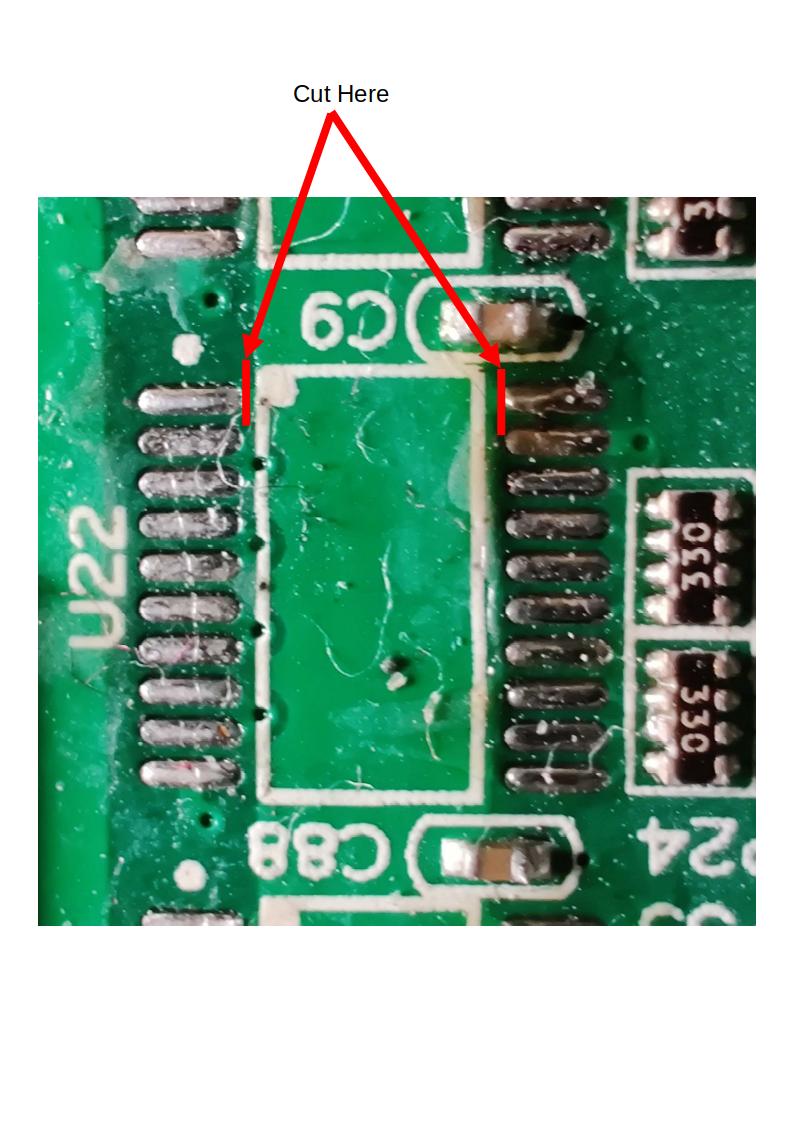
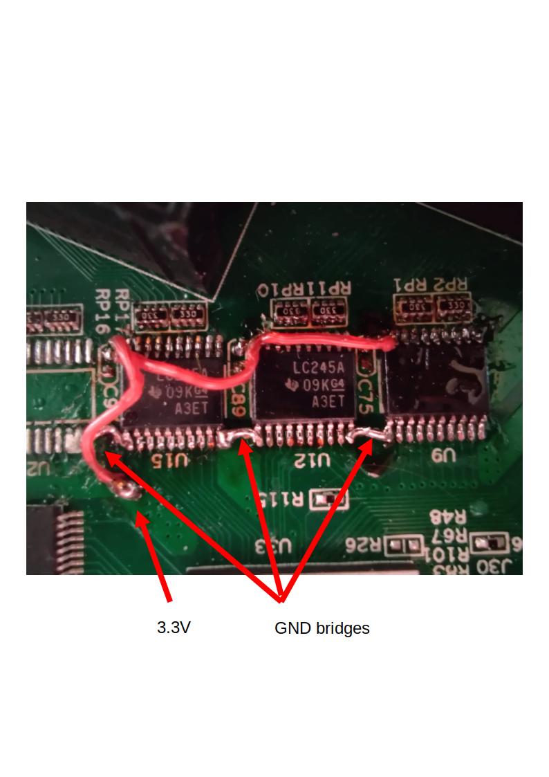
I'v removed the old buffers, cut the connection of pin 1 and 20 in order to rewire them.
Then soldered on the new buffers, connect pin 1 to pin 10 of the nearest chip (GND)
then connect pin 20 to 3V3 trace nearby.
This mod is IMHO a dirty hack, in future I'll replace buffer with simple bridges and
then connect external pcb with proper pull-up/downs, filtering and optocoupling as needed.
Attachments:
Please Log in or Create an account to join the conversation.
- TOLP2
- Offline
- Elite Member
-

- Posts: 225
- Thank you received: 178
Edit:
I resolved one of the bugs in GPIO (driver-side):
- by accident the last GPIO out pin was not written to the FPGA due to an error in the loop boundary.
- the same bug was also present in GPIO in, resolved there
- also stumbled on an error in GPIO in, which would cause dumping the core if the number of GPIO in was larger then the number of GPIO out pins.
I also started to rewrite the GPIO in and out for the firmware to resolve the error on the non-responsive GPIO inputs. Did some work on GPIO out, but didn't push it yet, as I could get the tests running on the RV901T. Tomorrow I'll switch back to my 5A-75E to check whether it is a problem with the card or the program.
Edit2:
I pushed the re-write of the GPIO. Tested voor GPIO out only, @muvideo could you give a try to get this working on your modified board.
Have to say that I found something which is 'less' nice from LiteX. The jumpers and pin-numbers are zero-based, so pin 1 on J1 should read J1:0. Costed me an evening to test why my GPIO was not working, was testing the wrong pins.
Please Log in or Create an account to join the conversation.
- muvideo
- Offline
- Senior Member
-

- Posts: 62
- Thank you received: 30
On GitHub i see only the commit 851b0de
Is this correct?
Please Log in or Create an account to join the conversation.
- svb
- Offline
- Senior Member
-

- Posts: 44
- Thank you received: 10
Try to make firmware and get this error
svb@LiteX-dev:~/CNC/LiteX-CNC/firmware$ python3 soc.py --build --no-compile
Traceback (most recent call last):
File "/home/svb/CNC/LiteX-CNC/firmware/soc.py", line 20, in <module>
from firmware.stepgen import StepGen
ModuleNotFoundError: No module named 'firmware'
svb@LiteX-dev:~/CNC/LiteX-CNC/firmware$
Where i can find module "firmware"?
Litex installed ok and more other projects builded ok
If i clone branch envoders, get another errors
svb@LiteX-dev:~/CNC/LitexCNC-e/firmware$ python3 soc.py --build --no-compile
Traceback (most recent call last):
File "/home/svb/CNC/LitexCNC-e/firmware/soc.py", line 9, in <module>
from .encoder import EncoderConfig
ImportError: attempted relative import with no known parent package
Best regards,
Sergey
Please Log in or Create an account to join the conversation.
- TOLP2
- Offline
- Elite Member
-

- Posts: 225
- Thank you received: 178
@svb: The problem lays in that you are one level to deep in the directory structure, i.e. you should be in the folder ~/CNC/LiteX-CNC/ and then run the following command:
python -m firmware /path/to/settings.jsonThe Pythonic explanation is that the firmware is a module (hence the -m tag) and is not designed to be used by running it directly. With the -m tag the code which resided in the __main__.py file is called. In some file you might see that it could be theoretically possible to run them directly (i.e if __name__ == '__main__', but those are present there only for testing purposes.
At this moment I recommend to use the `envoders` branch. These have the latest bug-fixes for issues contributed by this community.
Please Log in or Create an account to join the conversation.
- muvideo
- Offline
- Senior Member
-

- Posts: 62
- Thank you received: 30
Small testing update:
the bug on last output pin is solved, unfortunately I'm still not being successful at reading inputs. Verified the hardware with my own fw and the pins are being read ok.
Also I'm not able to get the stepgen to work.
Dont know if there is something wrong in my hal file, I uploaded it for your reference
a few messages back.
Small "problem" on pwm: if frequency is set to zero the pin will spit out a 25MHz square wave at 50% duty.
Thanks!
Fabio
Please Log in or Create an account to join the conversation.
- svb
- Offline
- Senior Member
-

- Posts: 44
- Thank you received: 10
Please Log in or Create an account to join the conversation.
- TOLP2
- Offline
- Elite Member
-

- Posts: 225
- Thank you received: 178
At this moment I have reproduced your problem with stepgen and am planning to solve this coming week. Not sure yet whether it is a problem with communication or the card.
About PWM: when the frequency is set to 0 it switches over to PDM (pulse density modulation), therefore you see a frequency of 25 MHz. It should still obey the enable and value pin, what were your inputs on these?
For the Gpio in: would you be willing able to run a modified version of the driver which prints out the received bytes from the card? This way we can pinpoint the problem to the card or driver. I can make a special branch for this tomorrow.
Please Log in or Create an account to join the conversation.
- muvideo
- Offline
- Senior Member
-

- Posts: 62
- Thank you received: 30
It would be useful to have a jtag bridge added to soc to peek at registers.
About PDM modulation, honestly didnt check the behavior changing the value, next time I'll do.
Edit about PDM:
I think has some initialization problem: the output is correct only after value becomes other than zero
in PDM mode (frequency zero). Otherwise the output will be 50% 25MHz whenever value is zero and frequency is zero.
After value becomes nonzero at least once in PDM mode, then the behavior is correct.
Please Log in or Create an account to join the conversation.


