Mesa 7I77 and Milltronics mill wiring
- brianTruck
-
 Topic Author
- Offline
- Premium Member
-

Less
More
- Posts: 99
- Thank you received: 6
12 Dec 2022 20:56 - 12 Dec 2022 21:11 #259269
by brianTruck
Mesa 7I77 and Milltronics mill wiring was created by brianTruck
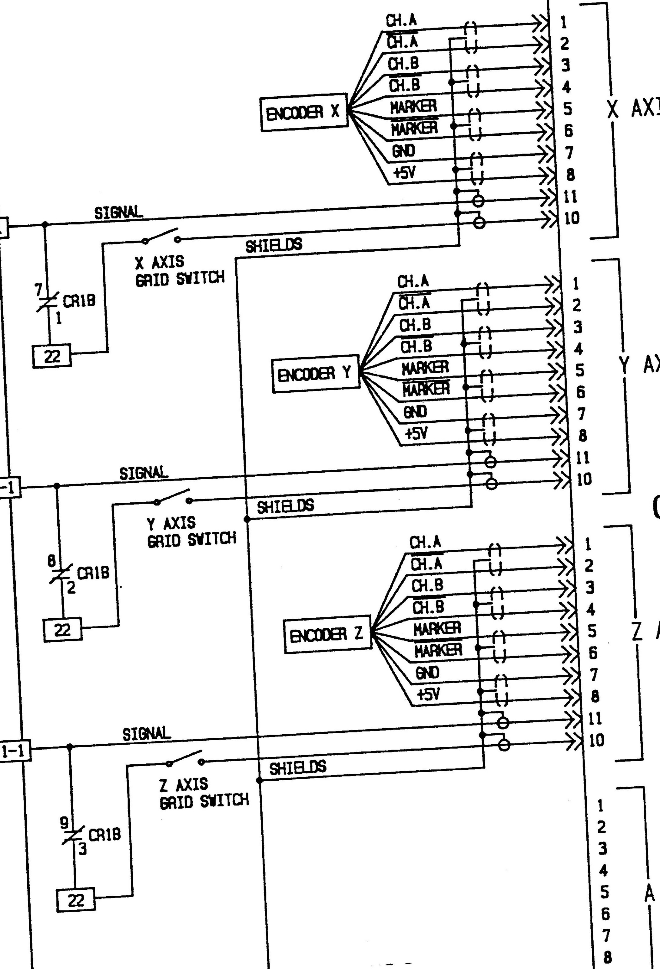
Hi, I've been collecting parts for when my old Dos controller for my Milltronics Mill decides to quit. I'm wiring up a new controller box with the 7i77 in it and I'm at a stand still with the analog drive wiring, the 7i77 has 4 outputs per drive and the glentec drives have only 2 inputs and how they are wired confuses me. here is a wiring diagram from the mill, can anyone tell me the correct way to connect the 7i77 to it?
Attachments:
Last edit: 12 Dec 2022 21:11 by brianTruck. Reason: fix photos
Please Log in or Create an account to join the conversation.
- Masiwood123
-

- Offline
- Platinum Member
-

Less
More
- Posts: 423
- Thank you received: 93
12 Dec 2022 21:56 - 12 Dec 2022 21:58 #259270
by Masiwood123
Replied by Masiwood123 on topic Mesa 7I77 and Milltronics mill wiring
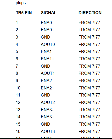
ena+, ena - is a floating switch, it means that the driver for a specific motor is enabled through it when you enable machine from linuxcnc.. if your driver is always enabled, you don't need to use ena i think..Gnd and Aout is the analog output signal from 0-10v(please read the manual for 7i77), I'm not sure how it is on your driver to connect correctly, someone from here who understands schematics better ,will add, i hope. greeting
Last edit: 12 Dec 2022 21:58 by Masiwood123.
Please Log in or Create an account to join the conversation.
- Masiwood123
-
- Offline
- Platinum Member
-
Less
More
- Posts: 423
- Thank you received: 93
12 Dec 2022 22:07 #259271
by Masiwood123
Replied by Masiwood123 on topic Mesa 7I77 and Milltronics mill wiring
I had a similar question, so maybe something on this post will help
pay attention to the fact that the 7i77 is sensitive to a short circuit and like that, i broke one like that... I advise you to try it on the driver first, maybe with a 1.5v battery to see if the motors start..
forum.linuxcnc.org/30-cnc-machines/44700...16-retrofit?start=30
pay attention to the fact that the 7i77 is sensitive to a short circuit and like that, i broke one like that... I advise you to try it on the driver first, maybe with a 1.5v battery to see if the motors start..
forum.linuxcnc.org/30-cnc-machines/44700...16-retrofit?start=30
Please Log in or Create an account to join the conversation.
- tommylight
-

- Away
- Moderator
-

Less
More
- Posts: 21686
- Thank you received: 7411
12 Dec 2022 23:38 #259275
by tommylight
Replied by tommylight on topic Mesa 7I77 and Milltronics mill wiring
Where does 22 and 1-1 go on the other pages?
Please Log in or Create an account to join the conversation.
- brianTruck
-
Topic Author
- Offline
- Premium Member
-
Less
More
- Posts: 99
- Thank you received: 6
12 Dec 2022 23:45 - 12 Dec 2022 23:47 #259276
by brianTruck
Replied by brianTruck on topic Mesa 7I77 and Milltronics mill wiring
1-1 is the servo drives and 22 is a multiple contact relay.
Last edit: 12 Dec 2022 23:47 by brianTruck.
Please Log in or Create an account to join the conversation.
- Masiwood123
-
- Offline
- Platinum Member
-
Less
More
- Posts: 423
- Thank you received: 93
12 Dec 2022 23:54 #259278
by Masiwood123
Replied by Masiwood123 on topic Mesa 7I77 and Milltronics mill wiring
To me, this looks like the right side is the driver... and the left side, exactly 1-1 and 22 wires come from that old controller, or am I wrong? do you have a more complete schematic, photo of the driver?
Please Log in or Create an account to join the conversation.
- brianTruck
-
Topic Author
- Offline
- Premium Member
-
Less
More
- Posts: 99
- Thank you received: 6
13 Dec 2022 00:03 #259281
by brianTruck
Replied by brianTruck on topic Mesa 7I77 and Milltronics mill wiring
Servo's on left, controller on right.
Please Log in or Create an account to join the conversation.
- Masiwood123
-
- Offline
- Platinum Member
-
Less
More
- Posts: 423
- Thank you received: 93
13 Dec 2022 00:18 - 13 Dec 2022 00:31 #259282
by Masiwood123
Replied by Masiwood123 on topic Mesa 7I77 and Milltronics mill wiring
yes, sorry, that's how it should be.. the encoder goes to the controller.. are there physically on the driver, apart from the input for the tacho 1-3 1-4, some two wires for the analog input somewhere?.. also does that old controller work at all, maybe jogging? there should be a pair of analog input wires on the driver.it seems to me that 1-1 is a common gnd.. and that 22 are + analog output... it just bothers me why it goes through the relay.. if the machine is already working, i would try to measure the voltage between 1-1 and 22
Last edit: 13 Dec 2022 00:31 by Masiwood123.
Please Log in or Create an account to join the conversation.
- Masiwood123
-
- Offline
- Platinum Member
-
Less
More
- Posts: 423
- Thank you received: 93
13 Dec 2022 00:39 #259283
by Masiwood123
Replied by Masiwood123 on topic Mesa 7I77 and Milltronics mill wiring
or maybe is 1-1 +analog input on driver..have no idea:(
Please Log in or Create an account to join the conversation.
- brianTruck
-
Topic Author
- Offline
- Premium Member
-
Less
More
- Posts: 99
- Thank you received: 6
13 Dec 2022 12:35 - 13 Dec 2022 12:36 #259308
by brianTruck
Replied by brianTruck on topic Mesa 7I77 and Milltronics mill wiring
So 22 is the ground plain, and the drives do not use individual enables as there is a system master enable. What concerns me is that it looks like on e-stop the relay pulls all the analog signals to 0, won't that short out the analog output of the 7i77 ( if it was at a positive voltage move?
Last edit: 13 Dec 2022 12:36 by brianTruck.
Please Log in or Create an account to join the conversation.
Moderators: PCW, jmelson
Time to create page: 1.136 seconds