Mesa 7I77 and Milltronics mill wiring
- brianTruck
-
 Topic Author
- Offline
- Premium Member
-

Less
More
- Posts: 99
- Thank you received: 6
13 Dec 2022 14:01 #259312
by brianTruck
Replied by brianTruck on topic Mesa 7I77 and Milltronics mill wiring
Would you run the analog signal through the enable pins so the if the e-stop was pushed the analog signal would disconnect from the drives or does the 7i77 disconnect the analog signal on estop internally?
Please Log in or Create an account to join the conversation.
- PCW
-

- Offline
- Moderator
-

Less
More
- Posts: 17946
- Thank you received: 5257
13 Dec 2022 14:53 - 13 Dec 2022 14:56 #259317
by PCW
Replied by PCW on topic Mesa 7I77 and Milltronics mill wiring
You could possibly damage the 7I77 card if you shorted all analog
outputs at once
If the analog enable hal pin is false, the 7i77's analog outputs are all set to 0V.
This and the drive enable(s) are the normal way motion is disabled when LinuxCNC
is not running or after a fault.
It's important that the global drive enable s is controlled by LinuxCNC,
so the the drives are not enabled until LinuxCNC is running and the position
feedback loop is closed, otherwise the drives may drift slowly.
Last edit: 13 Dec 2022 14:56 by PCW.
The following user(s) said Thank You: Masiwood123
Please Log in or Create an account to join the conversation.
- Masiwood123
-

- Offline
- Platinum Member
-

Less
More
- Posts: 423
- Thank you received: 93
13 Dec 2022 14:57 #259318
by Masiwood123
Replied by Masiwood123 on topic Mesa 7I77 and Milltronics mill wiring
I think it turns it off, i.e. I think it's 0v when the machine is not moving, regardless of whether it's enabled or estop is on. it is optional for you to find the wires that brought the analog voltage from the controller to the drivers, so that with some power source..battery or similar 0-10v, you can check whether the motors are started by applying the voltage. the other thing that worries me, and there are people who know, is is that signal the same for the 7i77 sourcing or sinking version of the card? do you have the exact manufacturer ,model number or tag of those drivers, or a more detailed schematic of the driver itself?
Please Log in or Create an account to join the conversation.
- brianTruck
-
Topic Author
- Offline
- Premium Member
-
Less
More
- Posts: 99
- Thank you received: 6
13 Dec 2022 15:23 #259321
by brianTruck
Replied by brianTruck on topic Mesa 7I77 and Milltronics mill wiring
These are the drives.
Please Log in or Create an account to join the conversation.
- Masiwood123
-
- Offline
- Platinum Member
-
Less
More
- Posts: 423
- Thank you received: 93
13 Dec 2022 16:05 - 13 Dec 2022 16:08 #259325
by Masiwood123
Replied by Masiwood123 on topic Mesa 7I77 and Milltronics mill wiring
4.4.3 SIGNAL INPUT:
The GA370 has two signal input configurations controlled by JP1. Configuration A (JP1 set on A) has two
single-ended inputs SIG. IN. (J1-2) and AUX. IN. (J1-1). Configuration B (JP1 set on") has one single-ended
has one single-ended
input AUX. IN (J1-1) and one differential input DIFF. IN (J2-1), DIFF. RET. (J2-2). (Refer to Appendix B,
drawing 370-3003). Typically when operating in the velocity mode, the input signal range is ±10 VDC. The
input voltage is summed with a precision DC tachometer to provide accurate velocity control at the servo motor
shaft (see fig. 3.1). The Signal Gain potentiometer RV2 (20 K), and Auxiliary Gain potentiometer RV1 (20 K),
adjust the motor velocity desired for a given input voltage velocity command (see 4.2 for recommended wire
type & size).
as I briefly looked at the manual, it seems that SigIN(1-2) or AuxIN(1-1) is an analog input if the factory drivers are set to A configuration..according to that, the power supply should be ..pin 4(GND) pin 2 (analog input voltage) I'm not sure, someone else on the forum if he can look at the instructions.. is your driver assembly all on one board, or are the driver cards separate for each axis? in any case, I would personally check the input with a lower voltage, say a 1.5v battery... if the motors turn, only then I would try via 7i77..
The GA370 has two signal input configurations controlled by JP1. Configuration A (JP1 set on A) has two
single-ended inputs SIG. IN. (J1-2) and AUX. IN. (J1-1). Configuration B (JP1 set on
has one single-endedinput AUX. IN (J1-1) and one differential input DIFF. IN (J2-1), DIFF. RET. (J2-2). (Refer to Appendix B,
drawing 370-3003). Typically when operating in the velocity mode, the input signal range is ±10 VDC. The
input voltage is summed with a precision DC tachometer to provide accurate velocity control at the servo motor
shaft (see fig. 3.1). The Signal Gain potentiometer RV2 (20 K), and Auxiliary Gain potentiometer RV1 (20 K),
adjust the motor velocity desired for a given input voltage velocity command (see 4.2 for recommended wire
type & size).
as I briefly looked at the manual, it seems that SigIN(1-2) or AuxIN(1-1) is an analog input if the factory drivers are set to A configuration..according to that, the power supply should be ..pin 4(GND) pin 2 (analog input voltage) I'm not sure, someone else on the forum if he can look at the instructions.. is your driver assembly all on one board, or are the driver cards separate for each axis? in any case, I would personally check the input with a lower voltage, say a 1.5v battery... if the motors turn, only then I would try via 7i77..
Last edit: 13 Dec 2022 16:08 by Masiwood123.
Please Log in or Create an account to join the conversation.
- Masiwood123
-
- Offline
- Platinum Member
-
Less
More
- Posts: 423
- Thank you received: 93
13 Dec 2022 16:15 #259326
by Masiwood123
Replied by Masiwood123 on topic Mesa 7I77 and Milltronics mill wiring
The following user(s) said Thank You: brianTruck
Please Log in or Create an account to join the conversation.
- brianTruck
-
Topic Author
- Offline
- Premium Member
-
Less
More
- Posts: 99
- Thank you received: 6
13 Dec 2022 16:53 - 13 Dec 2022 20:30 #259330
by brianTruck
Replied by brianTruck on topic Mesa 7I77 and Milltronics mill wiring
I altered the drawing of one axis to reflect how it is really wired (22 is ground).
Last edit: 13 Dec 2022 20:30 by brianTruck.
Please Log in or Create an account to join the conversation.
- Masiwood123
-
- Offline
- Platinum Member
-
Less
More
- Posts: 423
- Thank you received: 93
13 Dec 2022 18:32 - 13 Dec 2022 18:33 #259342
by Masiwood123
Replied by Masiwood123 on topic Mesa 7I77 and Milltronics mill wiring
pin number 1 seems ok to me and it should be + from the controller and auxIn on the driver.. but according to the driver semi here it says that pin 4 is the common ground for the tacho (otherwise it generates current when the motor turns and gives feedback to the driver on the pin 3), and for the analog input.. if that is the arrangement of the pins in reality, I would try to disconnect that 22 ground and try with the battery,
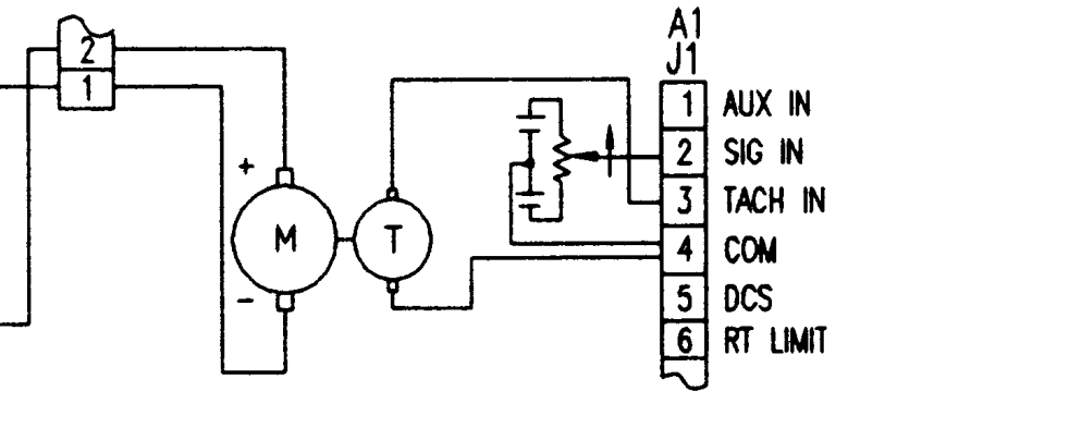 - on pin 4 and plus on pin 1. with protective gloves, rubber boots and a helmet of course-
")
Attachments:
Last edit: 13 Dec 2022 18:33 by Masiwood123.
Please Log in or Create an account to join the conversation.
- Masiwood123
-
- Offline
- Platinum Member
-
Less
More
- Posts: 423
- Thank you received: 93
13 Dec 2022 18:42 - 13 Dec 2022 18:44 #259344
by Masiwood123
Replied by Masiwood123 on topic Mesa 7I77 and Milltronics mill wiring
why 8? I also don't understand how this diode Cr on 22 is connected and what it is for..again need someone who understands to interpret it..Tomo help!
Last edit: 13 Dec 2022 18:44 by Masiwood123.
Please Log in or Create an account to join the conversation.
- Masiwood123
-
- Offline
- Platinum Member
-
Less
More
- Posts: 423
- Thank you received: 93
13 Dec 2022 19:01 #259346
by Masiwood123
Replied by Masiwood123 on topic Mesa 7I77 and Milltronics mill wiring
if one of your motors is free, you can try to spin it somehow, and measure if it gives any current between pins 4 and 3 (tacho), of course with the machine completely turned off.
Please Log in or Create an account to join the conversation.
Moderators: PCW, jmelson
Time to create page: 1.324 seconds