Wiring Mesa 7i96 + THCAD-5 with HF start plasma cutter
- alangibson
- Offline
- Premium Member
-

Less
More
- Posts: 95
- Thank you received: 36
25 Jan 2023 10:06 #262869
by alangibson
Wiring Mesa 7i96 + THCAD-5 with HF start plasma cutter was created by alangibson
Hello all,
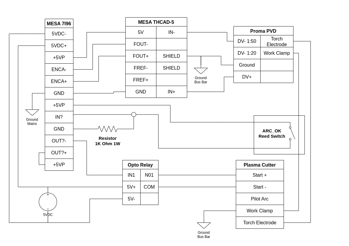
I'm putting together a plan to wire up a 7i96 and a THCAD-5 to my cheapo HF start pilot arc plasma cutter. I would appreciate it if you guys would call out my errors in the attached diagram before I let the smoke out of some hardware.
Plasma cutter: www.stahlwerk-schweissgeraete.de/Plasma-...er-CUT-40-Pilot-IGBT
Voltage divider: proma-elektronika.com/product/plasma-voltage-divider/
Opto isolated relay: www.amazon.com/HiLetgo-Channel-optocoupl...rigger/dp/B00LW15A4W
5V transformer: www.amazon.com/BANKEE-Converter-Voltage-...former/dp/B08NZV88MC
Attachments:
Please Log in or Create an account to join the conversation.
- rodw
-

- Away
- Platinum Member
-

Less
More
- Posts: 11970
- Thank you received: 4079
25 Jan 2023 11:28 #262873
by rodw
Replied by rodw on topic Wiring Mesa 7i96 + THCAD-5 with HF start plasma cutter
There may not be any need to add the Proma in the equation. Have a look in the thcad manual on how to scale the input.
Also the shield probably should not be connected to the thcad as it can introduce noise into the signal due to AC ripple
Normally, we use a THCAD-10 (to get a 0-10 volt fullscale) but using a THCAD-5 is OK if you already have ordered it.
Then add a scaling resistor to the THCAD to scale the raw voltage so 200 volts will give you a THCAD full scale reading.
Please Log in or Create an account to join the conversation.
- alangibson
- Offline
- Premium Member
-
Less
More
- Posts: 95
- Thank you received: 36
25 Jan 2023 13:21 #262879
by alangibson
Replied by alangibson on topic Wiring Mesa 7i96 + THCAD-5 with HF start plasma cutter
Thanks for the response rodw.
> Normally, we use a THCAD-10 (to get a 0-10 volt fullscale) but using a THCAD-5 is OK if you already have ordered it.
I would have preferred the THCAD-10, but I couldn't locate any here in Europe.
> There may not be any need to add the Proma in the equation. Have a look in the thcad manual on how to scale the input.
> Then add a scaling resistor to the THCAD to scale the raw voltage so 200 volts will give you a THCAD full scale reading.
I find myself wishing I hadn't bought the Proma PVD. In my case it's just acting like a big, expensive scaling resistor.
Following the THCAD manual, I should need a 3.9M Ohm resistor. Can I assume there are no special power requrements since it's not mentioned in the manual?
> Also the shield probably should not be connected to the thcad as it can introduce noise into the signal due to AC ripple
Are you referring to the connection between the THCAD-5 SHIELD terminal and the Proma PVD Ground terminal? My intention there was to have a star ground layout with a common bus bar connected to the table frame.
Please Log in or Create an account to join the conversation.
- JT
-

- Away
- Administrator
-

Less
More
- Posts: 1092
- Thank you received: 581
25 Jan 2023 23:47 #262912
by JT
Replied by JT on topic Wiring Mesa 7i96 + THCAD-5 with HF start plasma cutter
Shield wires are always only connected on one end otherwise your create a ground loop which can interfere with the signal.
JT
JT
Please Log in or Create an account to join the conversation.
- rodw
-
- Away
- Platinum Member
-
Less
More
- Posts: 11970
- Thank you received: 4079
26 Jan 2023 09:29 #262925
by rodw
Replied by rodw on topic Wiring Mesa 7i96 + THCAD-5 with HF start plasma cutter
Seeing you have the proma divider, you might as well use it on the 50:1 and no further scaling resistors will be required.
This will give you 250 volts full scale which is fine!
When cutting, it will never go over that. It may do so when percing very briefly when we don't care about the voltage then and it can handle 500 v overvoltage any way.
The THCAD does not seem as simple as that. In many countries, the electrical earth is bonded to the neutral in the meter box. If you connect the THCAD ground to the star ground (which is connected to the mains power electrical ground), you end up with a 50 or 60 Hz ripple introduced to the THCAD signal.
There are some threads on this somewhere.
Whether you shield the interconnect cable or not, its best not to ground the THCAD to the frame.
This will give you 250 volts full scale which is fine!
When cutting, it will never go over that. It may do so when percing very briefly when we don't care about the voltage then and it can handle 500 v overvoltage any way.
Shield wires are always only connected on one end otherwise your create a ground loop which can interfere with the signal.
JT
The THCAD does not seem as simple as that. In many countries, the electrical earth is bonded to the neutral in the meter box. If you connect the THCAD ground to the star ground (which is connected to the mains power electrical ground), you end up with a 50 or 60 Hz ripple introduced to the THCAD signal.
There are some threads on this somewhere.
Whether you shield the interconnect cable or not, its best not to ground the THCAD to the frame.
Please Log in or Create an account to join the conversation.
- tommylight
-

- Away
- Moderator
-

Less
More
- Posts: 21675
- Thank you received: 7404
26 Jan 2023 12:48 #262933
by tommylight
Replied by tommylight on topic Wiring Mesa 7i96 + THCAD-5 with HF start plasma cutter
THCAD high voltage side = no grounding.
THCAD low voltage/signal side grounded at the control box, not connencted to anything on the THCAD side.
On 12 or more machines in daily use, no issues, ever.
I mount THCAD on the back of the plasma source, always, in a plastic box.
THCAD low voltage/signal side grounded at the control box, not connencted to anything on the THCAD side.
On 12 or more machines in daily use, no issues, ever.
I mount THCAD on the back of the plasma source, always, in a plastic box.
Please Log in or Create an account to join the conversation.
- alangibson
- Offline
- Premium Member
-
Less
More
- Posts: 95
- Thank you received: 36
26 Jan 2023 13:14 #262938
by alangibson
Replied by alangibson on topic Wiring Mesa 7i96 + THCAD-5 with HF start plasma cutter
> Seeing you have the proma divider, you might as well use it on the 50:1 and no further scaling resistors will be required.
I've got another project that could probably use the Proma PVD, so I'm going to try to eliminate it from this circuit.
If I'm reading everyone correctly, the attached diagram should then work.
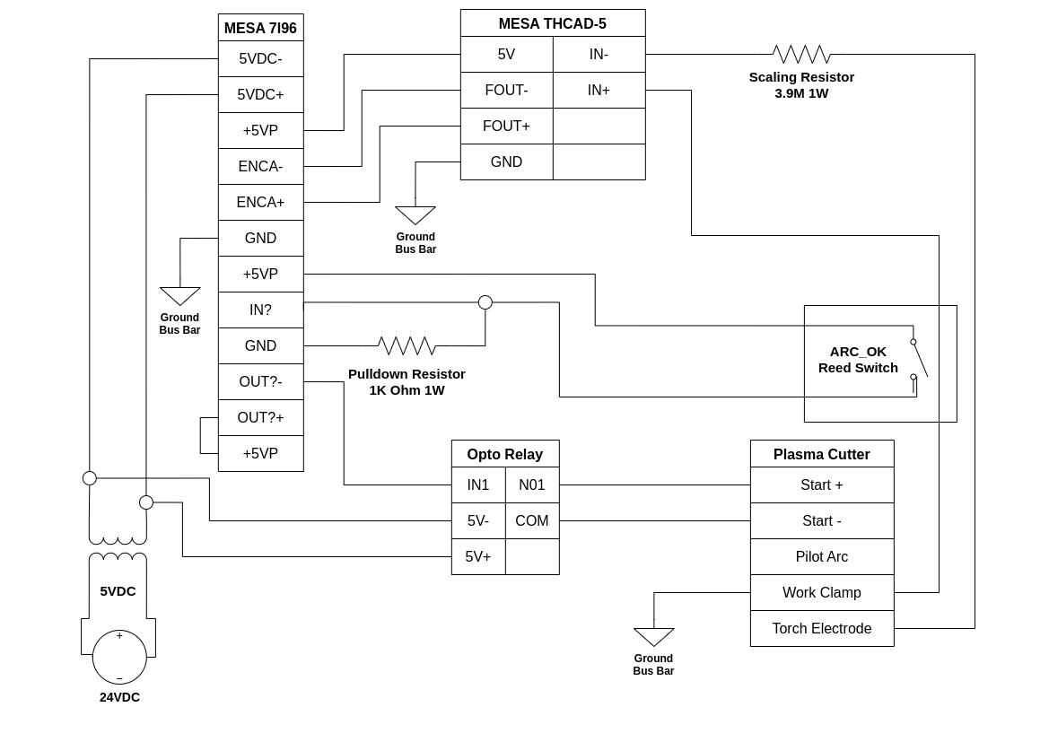
I've got another project that could probably use the Proma PVD, so I'm going to try to eliminate it from this circuit.
If I'm reading everyone correctly, the attached diagram should then work.
Attachments:
Please Log in or Create an account to join the conversation.
- rodw
-
- Away
- Platinum Member
-
Less
More
- Posts: 11970
- Thank you received: 4079
26 Jan 2023 18:28 #262950
by rodw
Replied by rodw on topic Wiring Mesa 7i96 + THCAD-5 with HF start plasma cutter
I make it 4.9 M for a 250 volt full scale
Split this in half and put half on each IN terminal
Also, you should be adding a seperate 24 V power supply for the 7i96 field power so the logic power and field power are isolated.
But there is a big problem with you plasma cutter! It is HF start! This is unsuited for the THCAD-5 directly ad it can catch fire from the 25k volts plus on starting. (Has happened here!)
It can only be used if you connect it internally in front of the HF starter. The proma manual shows this too. Tommy is the expoert here, So I'll let him guide you further.
Please Log in or Create an account to join the conversation.
- alangibson
- Offline
- Premium Member
-
Less
More
- Posts: 95
- Thank you received: 36
27 Jan 2023 08:30 #262990
by alangibson
Replied by alangibson on topic Wiring Mesa 7i96 + THCAD-5 with HF start plasma cutter
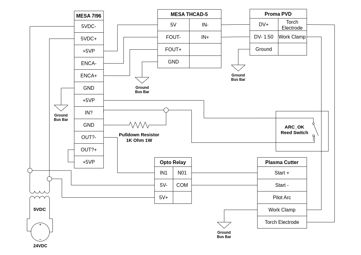
> This is unsuited for the THCAD-5 directly ad it can catch fire from the 25k volts plus on starting. (Has happened here!)
Ah, right. I had forgotten that this is the reason I added the Proma PVD in the first place. Their manual explicitly says that it's OK to connect it after the HF coil, though before is preferable. Maximum output voltage is 36V according to the specs.
My original plan was to have the THCAD and PVD external in a housing so that I could easy move it to another plasma cutter if I upgrade. I realize I might be getting too fancy here though.
That would leave me with the attached diagram (minus one extra power supply).
Attachments:
Please Log in or Create an account to join the conversation.
- alangibson
- Offline
- Premium Member
-
Less
More
- Posts: 95
- Thank you received: 36
27 Jan 2023 08:43 - 27 Jan 2023 08:45 #262992
by alangibson
Replied by alangibson on topic Wiring Mesa 7i96 + THCAD-5 with HF start plasma cutter
And in the case it's attached before the HF coil, it would look like this diagram.
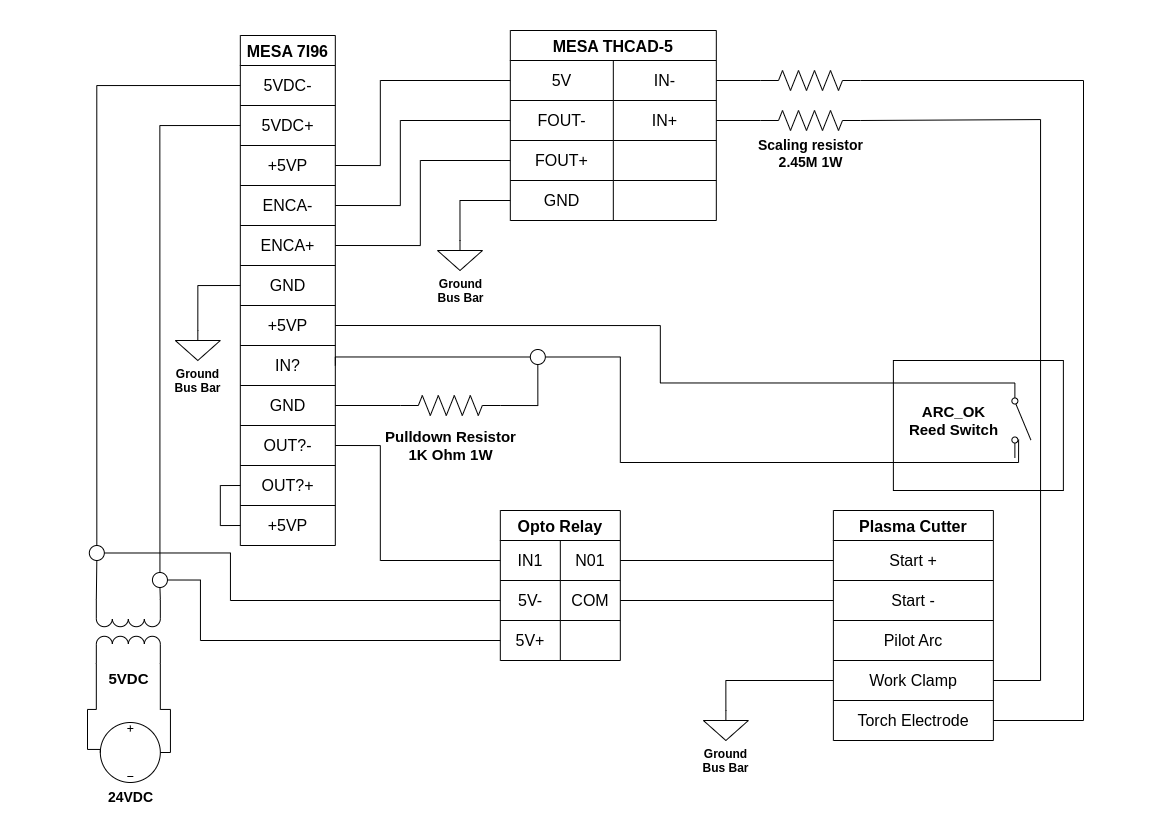
Attachments:
Last edit: 27 Jan 2023 08:45 by alangibson.
Please Log in or Create an account to join the conversation.
Moderators: PCW, jmelson
Time to create page: 0.217 seconds