7C81 - It appears that I have the wrong BOB, what now?
- MrRekt
- Offline
- New Member
-

Less
More
- Posts: 18
- Thank you received: 9
20 Jun 2023 06:28 #273898
by MrRekt
7C81 - It appears that I have the wrong BOB, what now? was created by MrRekt
I acknowledge
the other 7C81 thread
that's currently ongoing, but I'm starting another one to keep from crossing the streams.
I currently have a quasi-functional (meaning I'm not getting errors when launching LinuxCNC) setup with my Pi talking to the 7C81, which is flashed with the provided "5abobx2d.bit" file proved from the product-page.provides provides a copy of what is found in "5abobx2d.pin".That's well and good, except for the fact that it doesn't appear to be representative of the BOB I purchased:
If I'm understanding correctly (and I admit that this may not be the case), the pins indicated by the BOB's documentation are the physical pins the BOB expects Mach3 (because it's marketed to Mach3 users) to have configured to provide the advertised functionality. Those pins are connected to the P1 header on the 7C81 via a commercially-available adapter cable. Is there a degree of abstraction in the "Hardware Abstraction Layer" that is expected to accommodate for this discrepancy, or am I in need of a custom *.bit file?
NB. If it's of any help, the BOB I purchased is: www.amazon.com/dp/B07BFTRTBC
I currently have a quasi-functional (meaning I'm not getting errors when launching LinuxCNC) setup with my Pi talking to the 7C81, which is flashed with the provided "5abobx2d.bit" file proved from the product-page.
sudo mesaflash --device 7c81 --addr /dev/spidev0.0 --spi --readhmid. . .
Configuration pin-out:
IO Connections for P1+Serial
Pin# I/O Pri. func Sec. func Chan Pin func Pin Dir
0 0 IOPort PWM 0 PWM (Out)
0 1 IOPort None
0 2 IOPort StepGen 0 Step/Table1 (Out)
0 3 IOPort None
0 4 IOPort StepGen 0 Dir/Table2 (Out)
0 5 IOPort None
0 6 IOPort StepGen 1 Step/Table1 (Out)
0 7 IOPort None
0 8 IOPort StepGen 1 Dir/Table2 (Out)
0 9 IOPort StepGen 2 Step/Table1 (Out)
0 10 IOPort StepGen 2 Dir/Table2 (Out)
0 11 IOPort StepGen 3 Step/Table1 (Out)
0 12 IOPort StepGen 3 Dir/Table2 (Out)
0 13 IOPort None
0 14 IOPort QCount 0 Quad-A (In)
0 15 IOPort QCount 0 Quad-B (In)
0 16 IOPort QCount 0 Quad-IDX (In)
0 17 IOPort SSerial 0 TXData0 (Out)
0 18 IOPort SSerial 0 TXData1 (Out)
. . .# Summery of my BOB's LPT configuration
P1 PWM (spindle control)
P2 Output (spindle power relay)
P3 Output (coolent relay)
P5 Output (x axis direction)
P6 Stepgen (x axis step)
P7 Output (y axis direction)
P8 Stepgen (y axis step)
P9 Output (z axis direction)
P10 Stepgen (z axis step)
P11 Input (digital)
P12 Input (digital)
P13 Input (digital)
P14 Output (aux relay)
P15 Input (digital)
P16 Output (a axis direction)
P17 Stepgen (a axis step)
P18 GND
P19 GND
P20 GND
P21 GND
P22 GND
P23 GND
P24 GND
P25 GNDIf I'm understanding correctly (and I admit that this may not be the case), the pins indicated by the BOB's documentation are the physical pins the BOB expects Mach3 (because it's marketed to Mach3 users) to have configured to provide the advertised functionality. Those pins are connected to the P1 header on the 7C81 via a commercially-available adapter cable. Is there a degree of abstraction in the "Hardware Abstraction Layer" that is expected to accommodate for this discrepancy, or am I in need of a custom *.bit file?
NB. If it's of any help, the BOB I purchased is: www.amazon.com/dp/B07BFTRTBC
Please Log in or Create an account to join the conversation.
- tommylight
-

- Offline
- Moderator
-

Less
More
- Posts: 21686
- Thank you received: 7411
20 Jun 2023 11:23 #273916
by tommylight
Replied by tommylight on topic 7C81 - It appears that I have the wrong BOB, what now?
What does P4 do? It is missing on that list.
The BOB pinout seems very non standard, the usuall is pins 2-9 are always step/dir for XYZA.
The BOB pinout seems very non standard, the usuall is pins 2-9 are always step/dir for XYZA.
Please Log in or Create an account to join the conversation.
- MrRekt
- Offline
- New Member
-
Less
More
- Posts: 18
- Thank you received: 9
20 Jun 2023 14:05 - 20 Jun 2023 14:41 #273934
by MrRekt
It appears I made an error in my opening post regarding P4, P10, and P14, which should be corrected above.
The provided pinout table:

The provided pinout photo:

You may notice some discrepancies in these two images.
It appears that P14 may actually be the 3rd relay? P4 is listed in the photo as both a relay and a "shaft output" but the jumpers in the middle of the board have a note (look for the yellow arrow) calling it P14. Additionally, the "standby signals" for each of the relays account for P2, P3, and P14.
This leads me to think that - in spite of the table calling P4 a relay - it's likely intended to be used to drive a motor --- P4-9, 16, and 17 are labeled as "shaft output ports" in the photo...
Replied by MrRekt on topic 7C81 - It appears that I have the wrong BOB, what now?
# Summery of my BOB's LPT configuration
P1  PWM     (spindle control)
P2  Output  (spindle relay)
P3  Output  (coolant relay)
P4  Output  (motor control)
P5  Output  (motor control)
P6  Output  (motor control)
P7  Output  (motor control)
P8  Output  (motor control)
P9  Output  (motor control)
P10 Input   (digital)
P11 Input   (digital)
P12 Input   (digital)
P13 Input   (digital)
P14 Output  (aux relay)
P15 Input   (digital)
P16 Output  (motor control)
P17 Output  (motor control)
P18 GND
P19 GND
P20 GND
P21 GND
P22 GND
P23 GND
P24 GND
P25 GND
It appears I made an error in my opening post regarding P4, P10, and P14, which should be corrected above.
The provided pinout table:
The provided pinout photo:
You may notice some discrepancies in these two images.
It appears that P14 may actually be the 3rd relay? P4 is listed in the photo as both a relay and a "shaft output" but the jumpers in the middle of the board have a note (look for the yellow arrow) calling it P14. Additionally, the "standby signals" for each of the relays account for P2, P3, and P14.
This leads me to think that - in spite of the table calling P4 a relay - it's likely intended to be used to drive a motor --- P4-9, 16, and 17 are labeled as "shaft output ports" in the photo...
Last edit: 20 Jun 2023 14:41 by MrRekt. Reason: Added 2nd image. Fixing tons of errors introduced by the WYSIWYG.
Please Log in or Create an account to join the conversation.
- PCW
-

- Offline
- Moderator
-
Less
More
- Posts: 17946
- Thank you received: 5257
20 Jun 2023 14:57 - 20 Jun 2023 15:36 #273939
by PCW
Replied by PCW on topic 7C81 - It appears that I have the wrong BOB, what now?
It looks like the 5ABOB configuration would work if you use the P4 output for X axis step
bur would disable use of the relays (except if one is connected to P14)
You can get a better pinout listing if you update mesaflash
Here's a config that will allow you to use 2 relays
(or all 3 if you can actually use pin 14 for a relay)
This basically just moves stepgen 0 to 4,5 so
pins 2,3 are available for relays
Attachments:
Last edit: 20 Jun 2023 15:36 by PCW.
The following user(s) said Thank You: MrRekt
Please Log in or Create an account to join the conversation.
- MrRekt
- Offline
- New Member
-
Less
More
- Posts: 18
- Thank you received: 9
20 Jun 2023 17:09 - 20 Jun 2023 17:10 #273949
by MrRekt
Thank you!
Here's the pinout for P1 and P2, if anyone else happens to find themselves with the same bob:- and P7 is left open for IO
One more pinout related question before I get myself lost in the HAL file -
Does this type of ribbon-cable provide the necessary DCI26-to-DB25 wiring?:
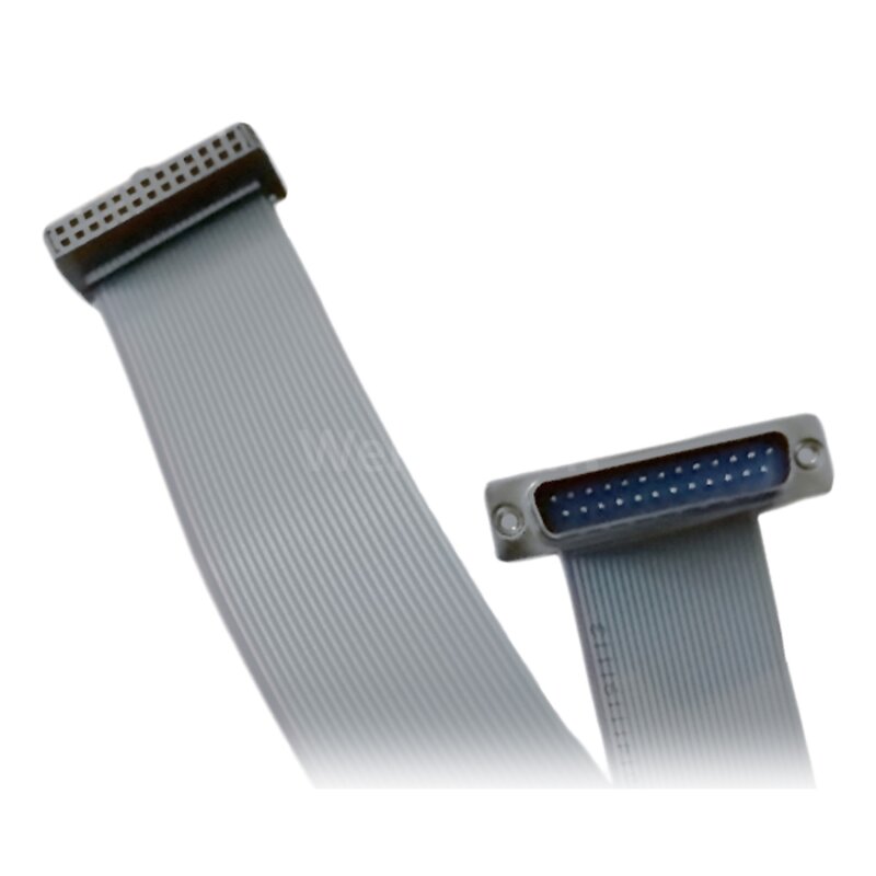
I'm not familiar with the numbering convention for standard headers...
Replied by MrRekt on topic 7C81 - It appears that I have the wrong BOB, what now?
Here's a config that will allow you to use 2 relays
(or all 3 if you can actually use pin 14 for a relay)
Thank you!
Here's the pinout for P1 and P2, if anyone else happens to find themselves with the same bob:
Configuration pin-out:

IO Connections for P1+Serial -> 7C81_0
Pin# I/O Pri. func Sec. func Chan Sec. Pin func Sec. Pin Dir

P1-01/DB25-01 0 IOPort PWM 0 PWM (Out)
P1-02/DB25-14 1 IOPort None
P1-03/DB25-02 2 IOPort StepGen 4 Step/Table1 (Out)
P1-04/DB25-15 3 IOPort None
P1-05/DB25-03 4 IOPort StepGen 4 Dir/Table2 (Out)
P1-06/DB25-16 5 IOPort StepGen 3 Step/Table1 (Out)
P1-07/DB25-04 6 IOPort StepGen 0 Step/Table1 (Out)
P1-08/DB25-17 7 IOPort StepGen 3 Dir/Table2 (Out)
P1-09/DB25-05 8 IOPort StepGen 0 Dir/Table2 (Out)
P1-11/DB25-06 9 IOPort StepGen 1 Step/Table1 (Out)
P1-13/DB25-07 10 IOPort StepGen 1 Dir/Table2 (Out)
P1-15/DB25-08 11 IOPort StepGen 2 Step/Table1 (Out)
P1-17/DB25-09 12 IOPort StepGen 2 Dir/Table2 (Out)
P1-19/DB25-10 13 IOPort None
P1-21/DB25-11 14 IOPort QCount 0 Quad-A (In)
P1-23/DB25-12 15 IOPort QCount 0 Quad-B (In)
P1-25/DB25-13 16 IOPort QCount 0 Quad-IDX (In)One more pinout related question before I get myself lost in the HAL file -
Does this type of ribbon-cable provide the necessary DCI26-to-DB25 wiring?:
I'm not familiar with the numbering convention for standard headers...
Last edit: 20 Jun 2023 17:10 by MrRekt. Reason: image tags
Please Log in or Create an account to join the conversation.
- PCW
-
- Offline
- Moderator
-
Less
More
- Posts: 17946
- Thank you received: 5257
20 Jun 2023 17:58 #273953
by PCW
Replied by PCW on topic 7C81 - It appears that I have the wrong BOB, what now?
Yes, that cable is correct (as long as HDR pin1 --> DB25 pin1).
Note that you need to disable stepgen 4 to get access to the relays
on DB25 pins 2,3: num_stepgens=4 or num_stepgens=3 if you only need 3 axis.
Note that you need to disable stepgen 4 to get access to the relays
on DB25 pins 2,3: num_stepgens=4 or num_stepgens=3 if you only need 3 axis.
The following user(s) said Thank You: MrRekt
Please Log in or Create an account to join the conversation.
- MrRekt
- Offline
- New Member
-
Less
More
- Posts: 18
- Thank you received: 9
28 Jun 2023 00:08 #274348
by MrRekt
Replied by MrRekt on topic 7C81 - It appears that I have the wrong BOB, what now?
I'm looking for signs of life in the I/O and haven't been able to find any -
(If I should open a new thread for this, please let me know...)
I ran:... and rebooted.
Then I ran:which gave meLooking in the PIN_ file, I see:
(just showing P1; simplified for clairity)And I ran the Pncconf Wizard with as many of the default settings as possible for a 3-step/dir and 1-PWM machine. I used INI substitution, unchecked any options under "Defaults and Options", and configured temporarily for "5i25-Internal Data" with "G540x2" almost identically to how it was done in this video (except for XYZ and not just XY):
I then adjusted the card name in the INI from "hm2_5i25" to "hm2_7c81", and updated the HAL file with "loadrt hm2_rpspi ..." to account for being on a RapsberryPi.
I then pulled out my oscilloscope to check for signs of life on the x-axis' step pin, as below:
I then proceeded to manually jog along the x-axis and looked to see if the oscilloscope saw anything as I did.
All it saw, at any resolution, was a solid 5.129 volts; no waveform at all...
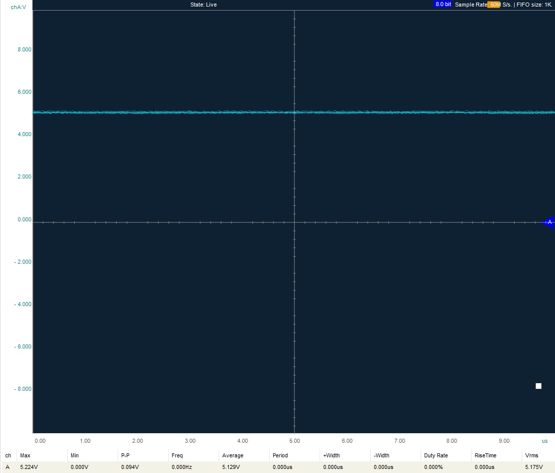
I check other pins in this manner, and it's all more-or-less the same story at 5 volts or 0 volts.
What am I doing wrong?
(If I should open a new thread for this, please let me know...)
I ran:
sudo mesaflash --device 7C81 --addr /dev/spidev0.0 --spi --fix-boot-block --write 7c81_c5abobx2d.bitThen I ran:
sudo mesaflash --device 7c81 --addr /dev/spidev0.0 --spi --readhmid...
Configuration pin-out:
IO Connections for P1+Serial -> 7C81_0
Pin# I/O Pri. func Sec. func Chan Sec. Pin func Sec. Pin Dir
P1-01/DB25-01 0 IOPort PWM 0 PWM (Out)
P1-02/DB25-14 1 IOPort None
P1-03/DB25-02 2 IOPort StepGen 4 Step/Table1 (Out)
P1-04/DB25-15 3 IOPort None
P1-05/DB25-03 4 IOPort StepGen 4 Dir/Table2 (Out)
P1-06/DB25-16 5 IOPort StepGen 3 Step/Table1 (Out)
P1-07/DB25-04 6 IOPort StepGen 0 Step/Table1 (Out)
P1-08/DB25-17 7 IOPort StepGen 3 Dir/Table2 (Out)
P1-09/DB25-05 8 IOPort StepGen 0 Dir/Table2 (Out)
P1-11/DB25-06 9 IOPort StepGen 1 Step/Table1 (Out)
P1-13/DB25-07 10 IOPort StepGen 1 Dir/Table2 (Out)
P1-15/DB25-08 11 IOPort StepGen 2 Step/Table1 (Out)
P1-17/DB25-09 12 IOPort StepGen 2 Dir/Table2 (Out)
P1-19/DB25-10 13 IOPort None
P1-21/DB25-11 14 IOPort QCount 0 Quad-A (In)
P1-23/DB25-12 15 IOPort QCount 0 Quad-B (In)
P1-25/DB25-13 16 IOPort QCount 0 Quad-IDX (In)
P5 3,6 17 IOPort SSerial 0 TXData0 (Out)
P6 3,6 18 IOPort SSerial 0 TXData1 (Out)
...(just showing P1; simplified for clairity)
...
              26 HDR    DB25
00 PWM        PIN 01    PIN 01    Spindle DAC PWM
00 Null       PIN 02    PIN 14    just GPIO
04 StepGen    PIN 03    PIN 02    B Step
00 Null       PIN 04    PIN 15    just GPIO
04 StepGen    PIN 05    PIN 03    B Dir
03 StepGen    PIN 06    PIN 16    A Step
00 StepGen    PIN 07    PIN 04    X Step
03 StepGen    PIN 08    PIN 17    A Dir
00 StepGen    PIN 09    PIN 05    X Dir
01 StepGen    PIN 10    PIN 06    Y Step
01 StepGen    PIN 11    PIN 07    Y Dir
02 StepGen    PIN 12    PIN 08    Z Step
02 StepGen    PIN 13    PIN 09    Z Dir
00 Null       PIN 14    PIN 10    Input 1 just GPIO
00 QCount     PIN 15    PIN 11    Input 2 (Quad A)
00 QCount     PIN 16    PIN 12    Input 3 (Quad B)
00 QCount     PIN 17    PIN 13    Input 4 (Quad Idx)

00 SSerial    I/O 17
00 SSerial    I/O 18
...I then adjusted the card name in the INI from "hm2_5i25" to "hm2_7c81", and updated the HAL file with "loadrt hm2_rpspi ..." to account for being on a RapsberryPi.
I then pulled out my oscilloscope to check for signs of life on the x-axis' step pin, as below:
I then proceeded to manually jog along the x-axis and looked to see if the oscilloscope saw anything as I did.
All it saw, at any resolution, was a solid 5.129 volts; no waveform at all...
I check other pins in this manner, and it's all more-or-less the same story at 5 volts or 0 volts.
What am I doing wrong?
Attachments:
Please Log in or Create an account to join the conversation.
- PCW
-
- Offline
- Moderator
-
Less
More
- Posts: 17946
- Thank you received: 5257
28 Jun 2023 00:21 #274349
by PCW
Replied by PCW on topic 7C81 - It appears that I have the wrong BOB, what now?
If all signal pins are at 5V I would suspect a watchdog bite.
(pins 18..25 should be grounded)
(pins 18..25 should be grounded)
Please Log in or Create an account to join the conversation.
- MrRekt
- Offline
- New Member
-
Less
More
- Posts: 18
- Thank you received: 9
28 Jun 2023 01:43 - 28 Jun 2023 02:54 #274351
by MrRekt
Replied by MrRekt on topic 7C81 - It appears that I have the wrong BOB, what now?
I went ahead and grounded pins 18-25, and no joy.
If if the watchdog was triggered, how do I check?
I assume that it would keep me from moving anything, but Hal Meter says steps are still being sent:
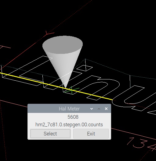
- edit -
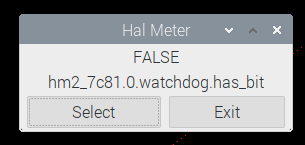
Doesn't seem to be the watchdog...
If it's any help, the only LOW pins are "X Dir" at 0.05V and "Z Dir" at 0.00V... "Y Dir" is HIGH for whatever reason. Even pins that I don't use are HIGH, like step and direction for both A and B axis. (I'm referencing the PIN_ file provided to me previously in this thread)
If if the watchdog was triggered, how do I check?
I assume that it would keep me from moving anything, but Hal Meter says steps are still being sent:
- edit -
Doesn't seem to be the watchdog...
If it's any help, the only LOW pins are "X Dir" at 0.05V and "Z Dir" at 0.00V... "Y Dir" is HIGH for whatever reason. Even pins that I don't use are HIGH, like step and direction for both A and B axis. (I'm referencing the PIN_ file provided to me previously in this thread)
Attachments:
Last edit: 28 Jun 2023 02:54 by MrRekt. Reason: Added additional notes.
Please Log in or Create an account to join the conversation.
- PCW
-
- Offline
- Moderator
-
Less
More
- Posts: 17946
- Thank you received: 5257
28 Jun 2023 13:45 #274390
by PCW
Replied by PCW on topic 7C81 - It appears that I have the wrong BOB, what now?
Can you check that All I/O pins are high when LinuxCNC is not running?
Please Log in or Create an account to join the conversation.
Moderators: PCW, jmelson
Time to create page: 0.204 seconds