- Hardware & Machines
- Driver Boards
- Can a 'servo drive' be used to power a 3 phase AC spindle motor with encoder?
Can a 'servo drive' be used to power a 3 phase AC spindle motor with encoder?
- bnet
-
 Topic Author
- Offline
- Senior Member
-

- Posts: 42
- Thank you received: 5
I'm trying to figure out if I can power a Fanuc 22P AC Spindle Motor [3 phase, 4 poles] with a suitably sized Allen & Bradley Ultra 3000 [Model #: 2098-DSD-075-SE]. Is it possible?
The application is a Hardinge Conquest retrofit, live tooling. I need to get decent positioning out of the spindle rotational axis to then lock (external lock, disk brake type) for cross drilling etc. Ideally I want to move towards full C axis but I think it wont be possible with this motor - correct me if I'm wrong.
Thanks!
Please Log in or Create an account to join the conversation.
- Cant do this anymore bye all
-

- Offline
- Platinum Member
-

- Posts: 1200
- Thank you received: 425
Pretty basic explanation, but comes down to motor construction.
Then again it might be best to contact the distributors/manufacturers.
Linuxcnc maybe able to control the VFD and close the loop for positioning purposes. Andy would have the wisest advice regarding this.
Please Log in or Create an account to join the conversation.
- spumco
- Offline
- Platinum Member
-
- Posts: 2120
- Thank you received: 880
The 3p Fanuc you're referring to is an induction motor. "AC servo" generally refers to a permanent magent synchronous motor. Not the same thing. And that U3K can't drive induction motors.
Of course, any motor (or actuator, really) that is controlled with a feedback loop can be considered a servo... but that's not really what you want to know.
The good news is that Fanuc can be driven with an ordinary VFD. Depending on the amps, you can even use a 240vac 1p to 3p VFD. You don't even need to replace the motor resolver - just leave it disconnected and run the motor open loop. My internet photo scraping indicates there's a separate encoder on the spindle... that's what LCNC will use to manage the motor speed and for threading/orientation.
But you're talking about a Conquest, not a toy lathe... so I'm guessing you're thinking about real work for real clients? If that's the case I wouldn't trust a VFD-brake-induction motor combo to position to a tight tolerance repeatably for production work. If you're making pipe flanges with a huge bolthole tolerance - no sweat.
Just think about how heavy the spindle is, plus the chuck, plus the work... and guesstimate the inertia ratio with a 1:1 belt drive... the whole arrangement will have a hard time stopping on a dime. And if you fiddle the belt ratio to get some torque, you'll kill the max spindle RPM.
It's likely that the original Fanuc spindle drive could position well enough for C-axis work, but those things are big money for a reason; they're basically servo drives for induction motors.
My guess is that the minute you stick an end mill in a radial holder and try to cut a circumferential groove/feature the aftermarket VFD won't be able to handle it. Same for polar interpolation with an axial tool (making a hex out of round with the X/C-axes).
[side note: LCNC doesn't have 'built-in' polar interpolation. It can be done, but it's non-trivial to accomplish]
Others may have a different opinion, but mine is that for dynamic C-axis lathe work you need a separate positioning motor as well as a spindle-mounted high-res encoder. My Emco CNC lathe uses a pneumatic cylinder to swing the C-axis positioning motor in to mesh with a large bull gear on the spindle. I think it's about 40:1 - maybe more. The constant air pressure keeps backlash to a minimum, but also makes it noisy and limits the C-axis top speed.
For little lathes (like the one I'm building - think HLV-H size), a big AC servo and a favorable belt ratio can work for positioning and light off-axis milling/engraving, but that's about it. Unless the servo is massively oversized it just won't have enough torque for tight-tolerance work against unfavorable machining forces.
So to sum up - a VFD will spin that Fanuc. And should do positioning OK (with the brake) for axial/radial drilling. But i don't think it'll work for dynamic C-axis work, and the positioning accuracy may not meet your tolerance requirements
Just my two cents...
Please Log in or Create an account to join the conversation.
- bnet
-
Topic Author
- Offline
- Senior Member
-
- Posts: 42
- Thank you received: 5
I was wrongly under the impression that CNC lathes with mill/turn spindle action were positioned and run by just 1 beefy servo, but in fact it seems like this would be a somewhat rare case for a high-holding-power or high-feed-power system. A little more research has led me to a video by EdgePrecision on youtube who describes how his C axis on the Mazak Integrex works - it features a hydraulically-actuated worm gear that comes in to engagement when the machine is set to full C-axis milling mode. See here:
This will place 'full C-axis' outside of the immediate plans for this lathe.
Definitely not a toy or hobby machine, and my goal is to get it as productive as possible for real clients and production - the hope is to make it as versatile as possible. Machine is also equipped with a 12ft bar feeder.But you're talking about a Conquest, not a toy lathe...
Yes, it has an external spindle encoder, resolution unknown at the moment. If I have to get a VFD and run it open-loop that is an option, with the encoder being used for turning threads and positioning for 2+1 work with live tools. Original positioning accuracy was stated to be within a degree. There might even be lock pins or something degree wise, I'm seeing something in the schematics saying spindle pin odd/even. I will look into that later.
The machine is currently equipped with the original Fanuc control and all of the Fanuc drivers and motors are installed and in functional shape. The control is aging and already causing issues that I don't want to have to become a Fanuc expert to repair.
It's likely that the original Fanuc spindle drive could position well enough for C-axis work, but those things are big money for a reason; they're basically servo drives for induction motors.
The original Fanuc drive is currently in there and hooked up, working. I wonder if I can make it work with LinuxCNC. Currently is connected through an optical cable but maybe there are different modes of command. It would be great to not have to swap out the drive but I'll do what I have to do if needed - I will have to swap out the axis', turret, and live tool drives because of the unsolved riddle of communicating with Fanuc drives from LinuxCNC. Oh well. Whatever makes it work.
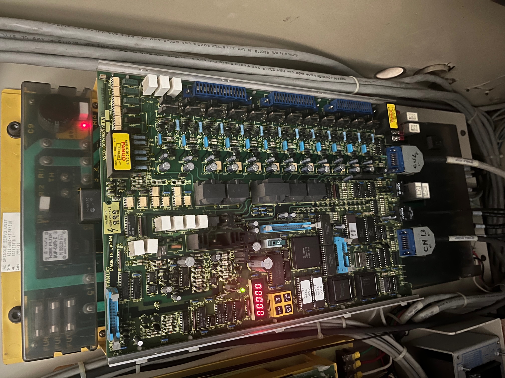
I have attached a photo of the spindle drive currently installed [Fanuc A06B-6063-H215#510]. Does anyone have any experience controlling this type of drive with LinuxCNC?
Thanks again.
Attachments:
Please Log in or Create an account to join the conversation.
- spumco
- Offline
- Platinum Member
-
- Posts: 2120
- Thank you received: 880
Regarding the C-axis aux motor, I just stumbled on a <shall-not-be-named> forum post where someone retrofitted a Fanuc lathe and added an aux C-axis motor. They did, more or less, something I'd been thinking about for a bit: belt drive with dog-clutch.
centroidcncforum.com/viewtopic.php?f=57&...1&hilit=fanuc#p88931
Looks like they crammed the clutched C-axis servo in the main spindle drive belt path, added a couple idlers for belt tension, and just used longer belts. Quite clever, and doesn't need a separate belt or gear drive.
Please Log in or Create an account to join the conversation.
- bnet
-
Topic Author
- Offline
- Senior Member
-
- Posts: 42
- Thank you received: 5
Wow, this is a neat implementation! Fairly simple and seems to work well. Gets me thinking about my solution. Going to take some cramming to fit it all in the space I have around the spindle but it just might work.centroidcncforum.com/viewtopic.php?f=57&...1&hilit=fanuc#p88931
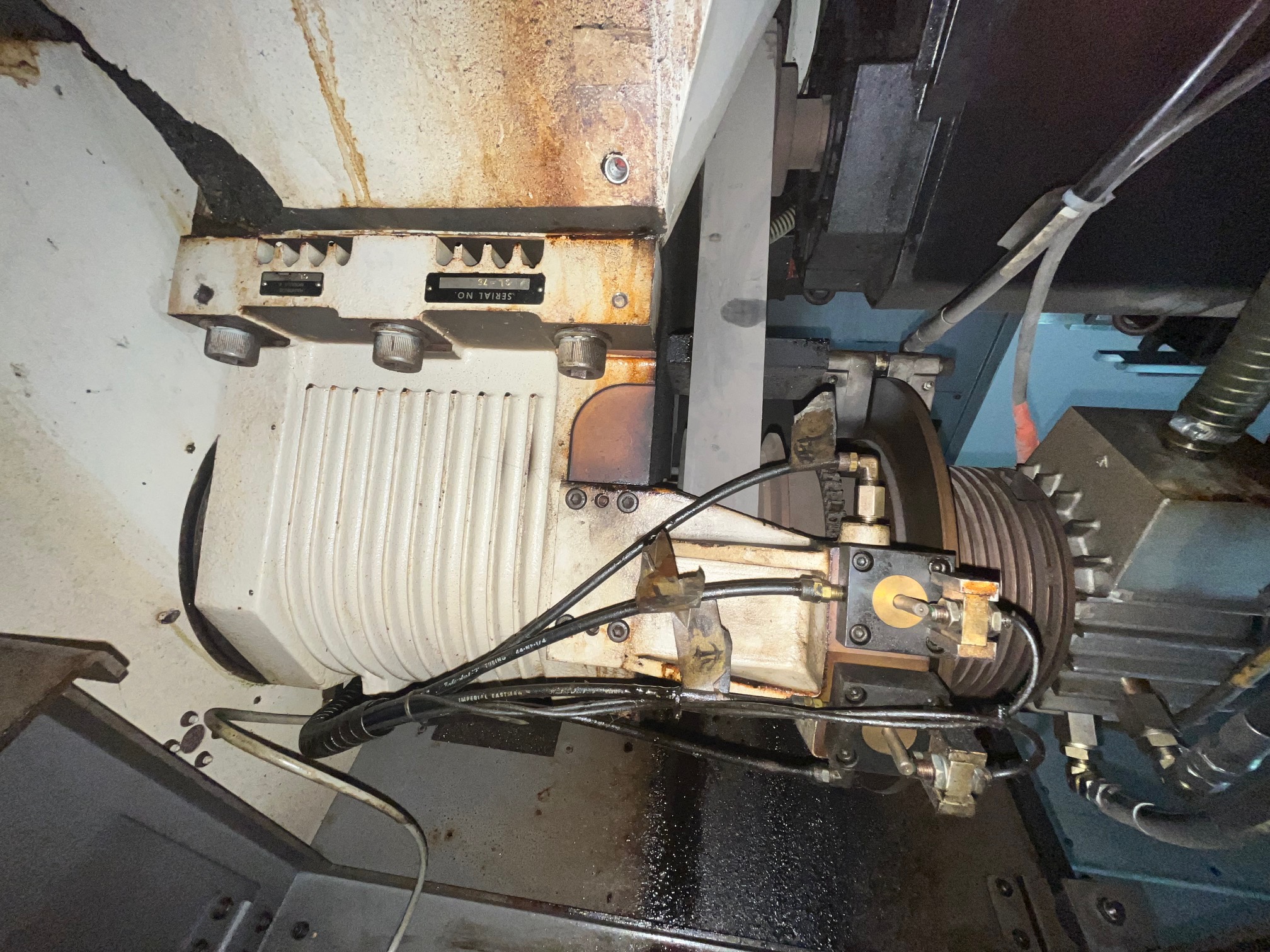
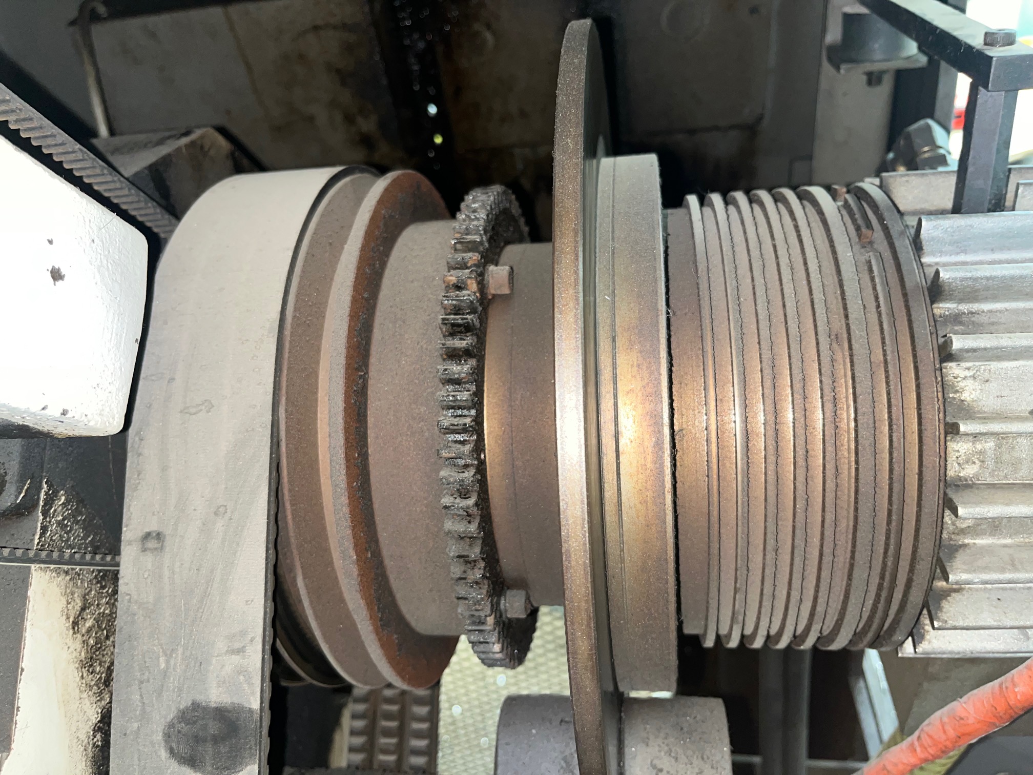
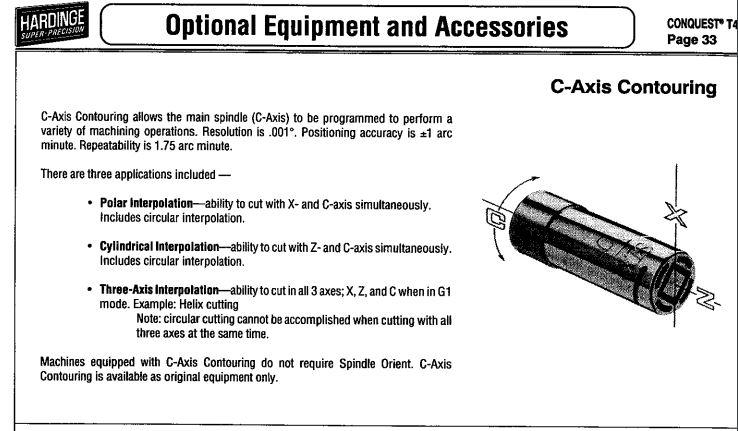
Some photos of the Hardinge Conquest spindle for those interested. This machine has an epoxy/granite base that you can see a little chunk broken off of in one of the photos. There is a gear-looking ring on the spindle that two separate pins can engage with (odd/even labels in documentation, maybe that stands for odd/even degrees based on their offset). Makes me think that a retractable worm drive could be fitted there in place of this system but that definitely seems more mechanically involved as it would have to be all custom. I wonder how Hardinge did their Conquests with full C axis..
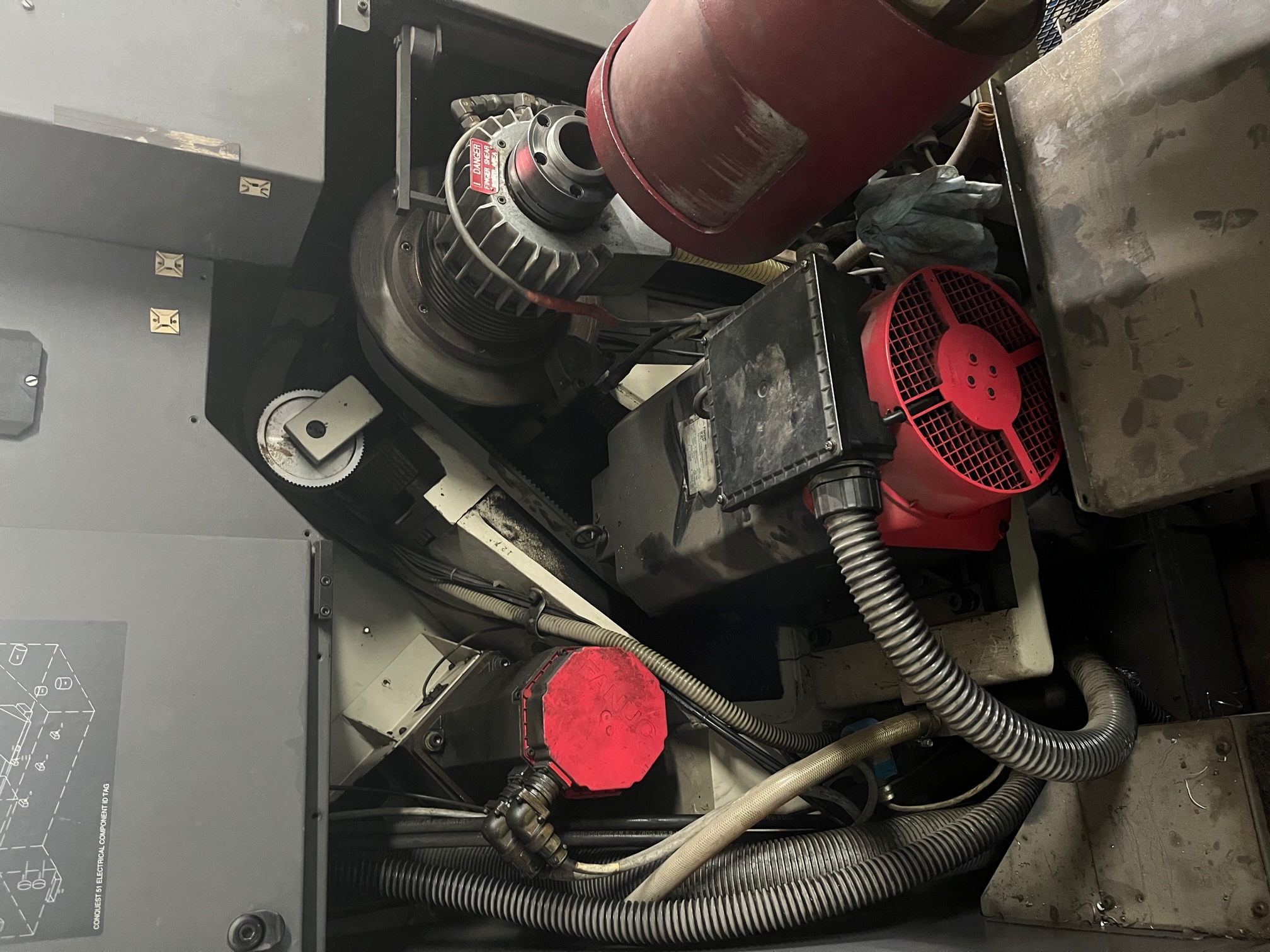
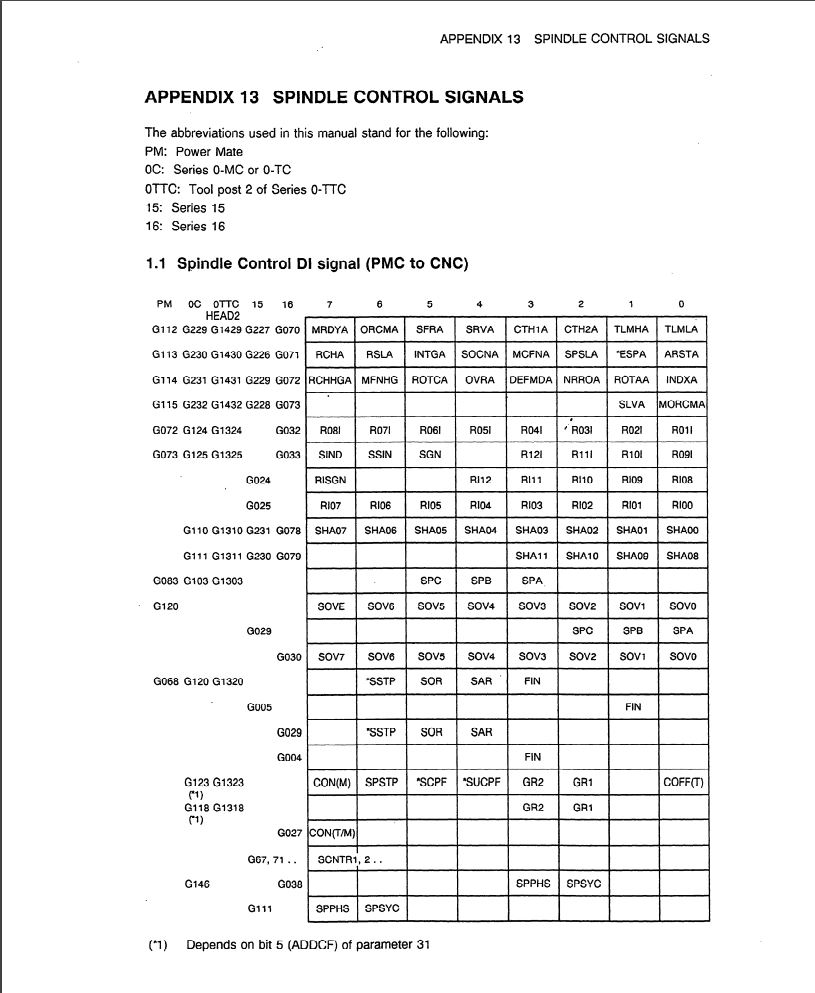
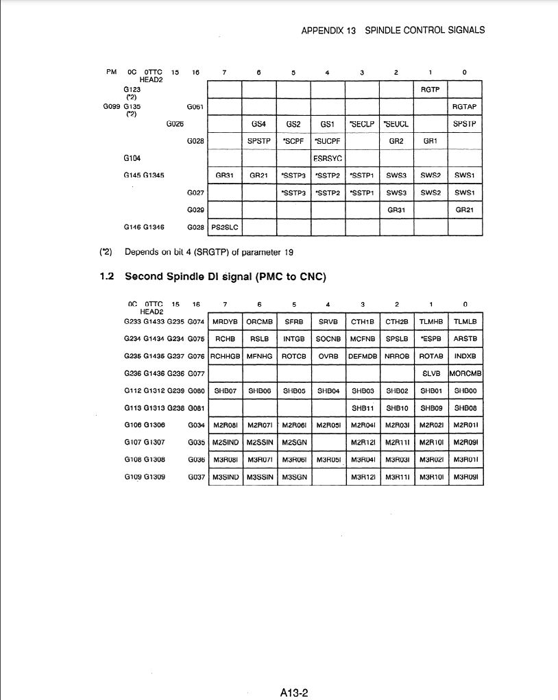
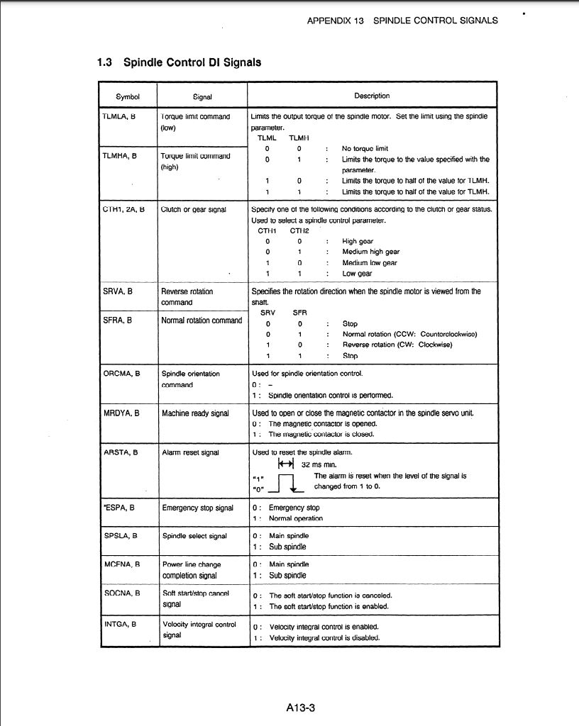
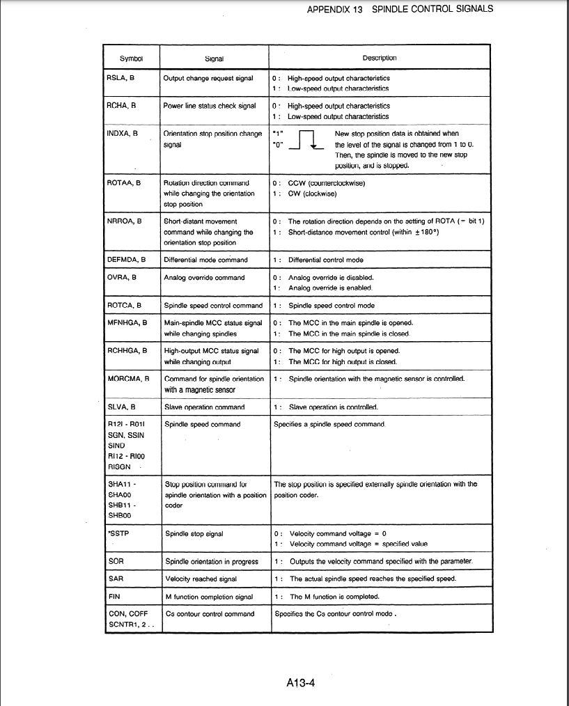
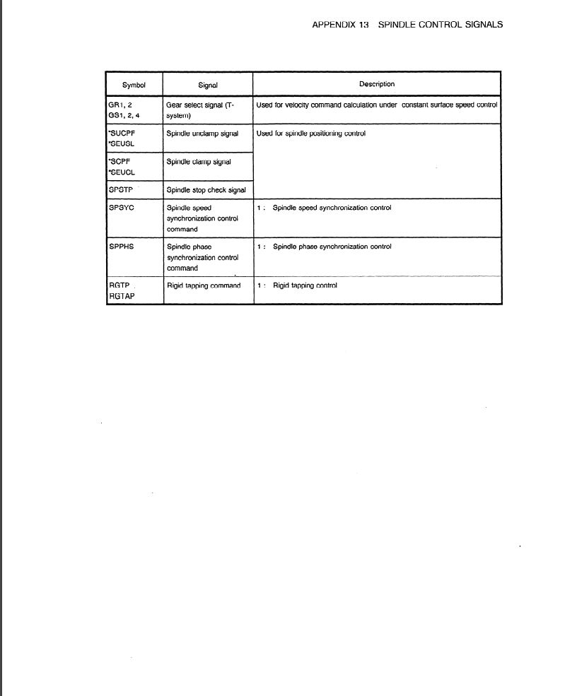
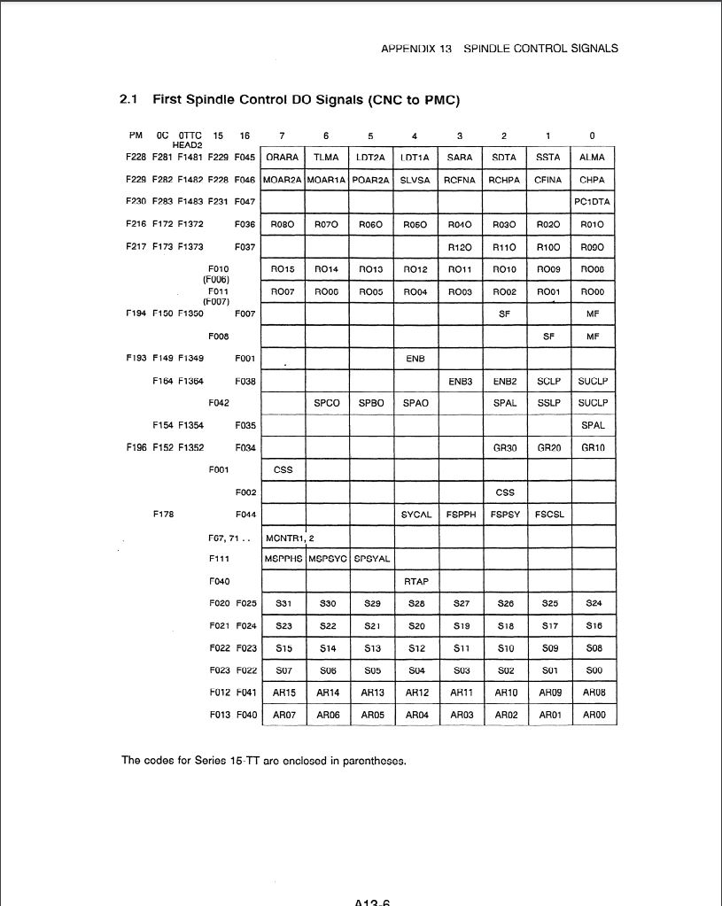
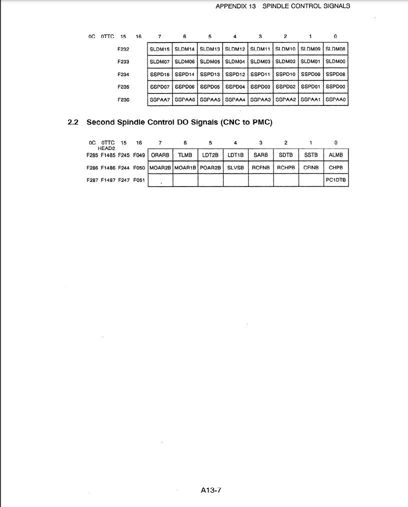
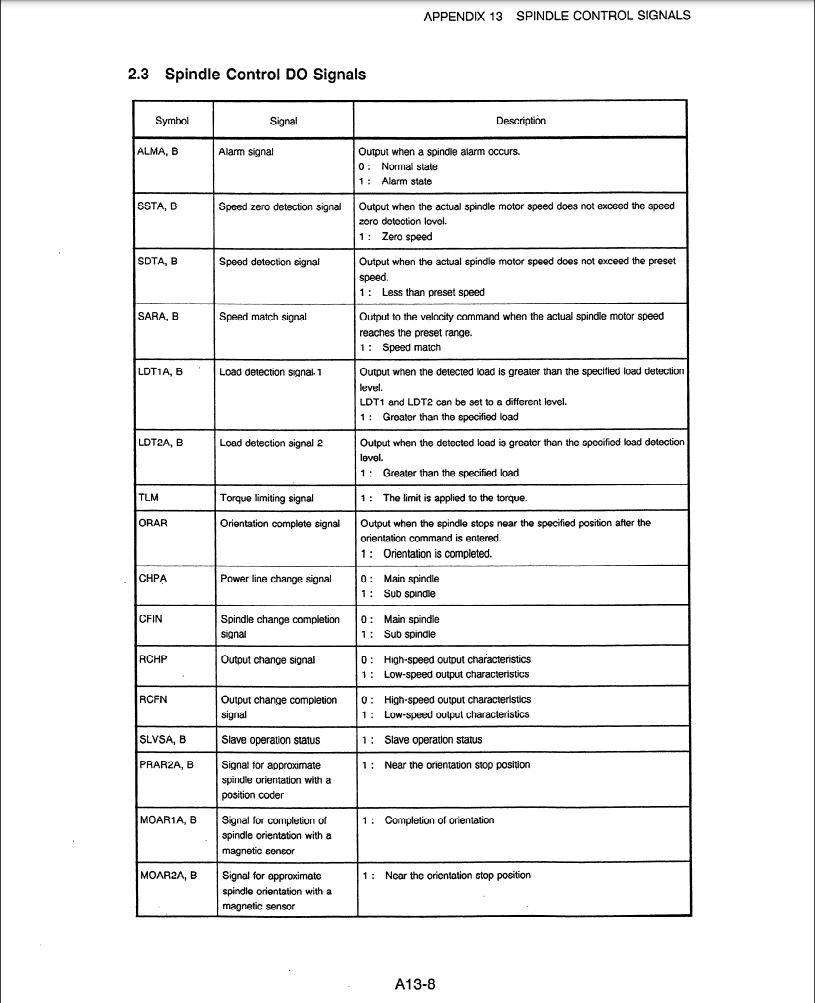
Yes, very tricky to track down the Fanuc docs, mainly seems to be that they put a huge number of products in a single doc. I managed to track down the spindle amp documentation if anyone wants to see that. 400 pages or so, the forum wouldn't upload it so get in touch if you want me to send it over.It's hard to find anything clear on Fanuc stuff, but I think the spindle amp uses serial communication to/from the Fanuc control. So while it may be possible...
Attachments:
Please Log in or Create an account to join the conversation.
- bnet
-
Topic Author
- Offline
- Senior Member
-
- Posts: 42
- Thank you received: 5
Attachments:
Please Log in or Create an account to join the conversation.
- bnet
-
Topic Author
- Offline
- Senior Member
-
- Posts: 42
- Thank you received: 5
Attachments:
Please Log in or Create an account to join the conversation.
- spumco
- Offline
- Platinum Member
-
- Posts: 2120
- Thank you received: 880
The pins are strange. Pneumatic lines to actuators, and proxy sensors if the pins are retracted... fishy. No idea what they do, other than maybe they're part of an alignment mechanism.
Hypothesis: Perhaps when C-axis is commanded, the main spindle rotates slowly to the encoder index, then one of the pins drops in place (indicating gear alignment with axis servo), then is retracted with the air after the C-axis servo is swung in to engage the bull gear. That way the gear alignment isn't dependent on the encoder index pulse if the belt is replaced.
If you can find a pic of another lathe I bet you'll see a servo and some sort of swing-arm bracket so a spur gear on the servo can be brought in to mesh with the spindle gear using an air or hydraulic cylinder. Just like the miniature version on my lathe.
I think asking on Practical Machinist would be your best bet, or call Hardinge and see if they've got any older repair/parts manuals.
Please Log in or Create an account to join the conversation.
- bnet
-
Topic Author
- Offline
- Senior Member
-
- Posts: 42
- Thank you received: 5
Could be the case! I'm thinking that it is mostly just a hard-index system for the C-positioning feature. Maybe it could be used for full C though, will have to look into the type of geometry that is usually used for that kind of worm gear.The pins are strange. Pneumatic lines to actuators, and proxy sensors if the pins are retracted... fishy. No idea what they do, other than maybe they're part of an alignment mechanism.
Hypothesis: Perhaps when C-axis is commanded, the main spindle rotates slowly to the encoder index, then one of the pins drops in place (indicating gear alignment with axis servo), then is retracted with the air after the C-axis servo is swung in to engage the bull gear. That way the gear alignment isn't dependent on the encoder index pulse if the belt is replaced.
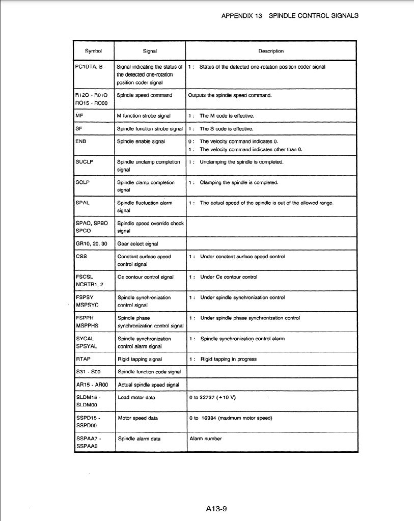
Here's what the parts manual has to say about the indexing system we speak of:
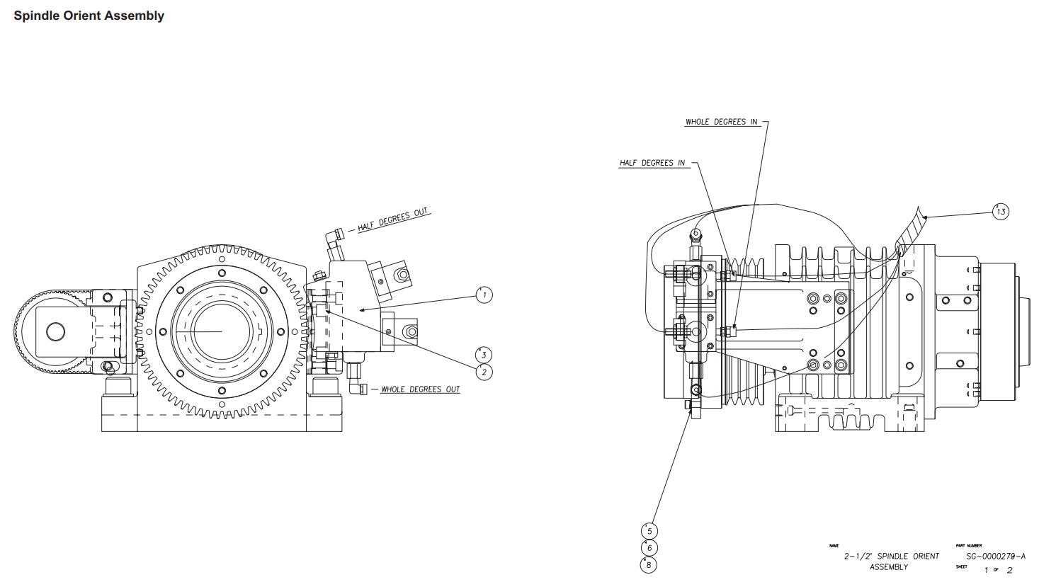
The parts diagrams can be viewed here:
shop.hardinge.com/medias/sys_master/imag...PLA-0009500-0060.pdf
Strangely, the component list/diagrams that Hardinge offers do not say anything about the original equipment used in the c-axis contouring option, yet it outlines parts for every other optional add-on.
Maybe I'll give Hardinge a call or ask on Practical Machinist. Either way my implementation will have to be something I can pull off and integrate into the LinuxCNC environment.
Attachments:
Please Log in or Create an account to join the conversation.
- Hardware & Machines
- Driver Boards
- Can a 'servo drive' be used to power a 3 phase AC spindle motor with encoder?