Fanuc servo drive integration
- Diederik
-

- Offline
- Premium Member
-

- Posts: 142
- Thank you received: 2
Please Log in or Create an account to join the conversation.
- andypugh
-

- Offline
- Moderator
-

- Posts: 19861
- Thank you received: 4636
But: I am not using PWM and I am not using Fanuc motors.
The similarity is that I am using the "bldc" HAL component to do the commutation.
The new thing you need to get used to is not the difference between pwm and analogue. You need to understand commutation of brushless motors.
The 7i80 or 7i90 would work, if you could make the right firmware for them. The reason I was suggesting the 5i23 is that a suitable firmware already exists.
Please Log in or Create an account to join the conversation.
- jCandlish
-

- Offline
- Senior Member
-

- Posts: 77
- Thank you received: 4
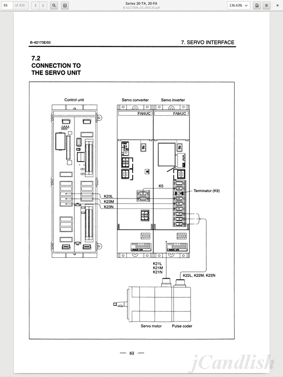
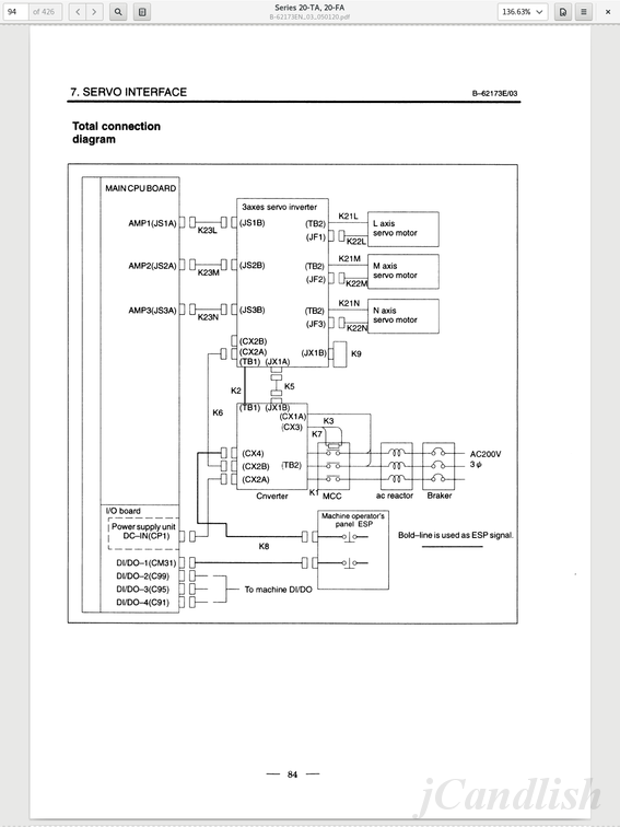
It is unclear to me if by servo "drive' you me "motor" or "amplifier". In FANUC nomenclature a "servo amplifier" is called a "servo inverter".
There are two connections from a FANUC servo inverter to each axis servomotor. One for the positional encoder, and a second for BLDC phase signals.
From the inverter to the controller there is a single cable that multiplexes state information from the inverter and BLDC phase information from the controller.
Do you have the FANUC "Connection Manual" for the series of control that you are retrofitting?
The Connection Manual describes the electrical and structural specifications for connecting a FANUC control to a machine tool.
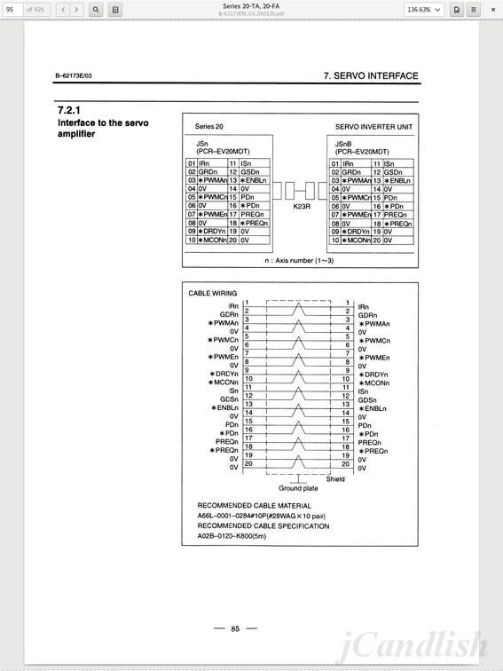
Here are some scans that you might find helpfull:
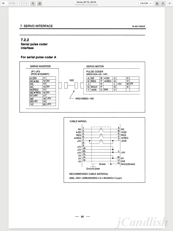
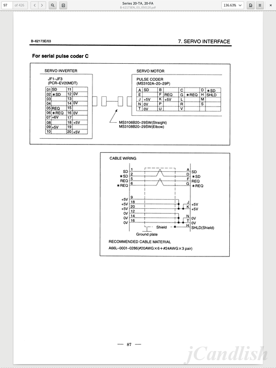
The inverter keeps track of the absolute position of each servomotor, even when the machine is off, by means of battery back up. Even when an axis is moved.
How the inverter communicates the absolute axis position upstream to the control is a mystery???
It is well worth reading this whole thread over from the beginning. Especially the part about the serial position encoders.
Edit: Also, FANUC handles spindle servos differently than axis servos!
Please Log in or Create an account to join the conversation.
- jmelson
- Offline
- Moderator
-
- Posts: 520
- Thank you received: 126
How the inverter communicates the absolute axis position upstream to the control is a mystery???
Actually, the absolute position comes from the encoder. The servo amp has a backup battery that keeps power on part of the encoder, to save the last position. The Fanuc serial encoders report absolute position to the servo amp as a 77-bit serial stream. This contains an angluar position count plus a count of the number of turns from the reference position. The encoders with a model that ends in "A" also have a low-resolution absolute data track that gives 1024 counts/quadrant. This can be used to provide commutation info the the servo amp even after the battery power has been interrupted. The angular position data has different resoultion depending one encoder model number. They go from 32768 counts/rev up to 1048576 counts/rev.
I'm pretty sure the data between the control and amplifier are also serial, but I do not know the protocol.
Jon
Please Log in or Create an account to join the conversation.
- jCandlish
-
- Offline
- Senior Member
-
- Posts: 77
- Thank you received: 4
I'm pretty sure the data between the control and amplifier are also serial, but I do not know the protocol.How the inverter communicates the absolute axis position upstream to the control is a mystery???
Exactly the mystery! According to my documentation, and on inspection of my machine, there is only the K23R connector between the inverter and controller. Despite searching, I have seen no serial communication documentation callout for any line of that cable!?
Please Log in or Create an account to join the conversation.
- PCW
-

- Offline
- Moderator
-
- Posts: 17919
- Thank you received: 5247
To make an interface, at least using Mesa hardware, would require a custom daughtercard that:
1. Buffers the FPGA signals to full 5V 24ma levels (and also supports differential output for some Fanuc drives)
2. Has protected Schmitt trigger 5V inputs
3. Handles the bidirectional nature of the PWM lines (they return drive status bits when DRDY is not asserted)
4. Has a 2 channel per Axis simultaneous sampling A-D for reading IS and IR so FOC can be implemented
Either in the FPGA or LinuxCNC (IS and IR are analog +-4.4V FS phase currents)
Please Log in or Create an account to join the conversation.
- jCandlish
-
- Offline
- Senior Member
-
- Posts: 77
- Thank you received: 4
That is why I am particularly interested in the discoveries of others on this front.
Please Log in or Create an account to join the conversation.
- andypugh
-
- Offline
- Moderator
-
- Posts: 19861
- Thank you received: 4636
1. Buffers the FPGA signals to full 5V 24ma levels (and also supports differential output for some Fanuc drives)
2. Has protected Schmitt trigger 5V inputs
3. Handles the bidirectional nature of the PWM lines (they return drive status bits when DRDY is not asserted)
4. Has a 2 channel per Axis simultaneous sampling A-D for reading IS and IR so FOC can be implemented
Either in the FPGA or LinuxCNC (IS and IR are analog +-4.4V FS phase currents)
This is sounding rather more involved than I had assumed. I had thought that these motors had the old 4-wire commutation output.
Please Log in or Create an account to join the conversation.
- PCW
-
- Offline
- Moderator
-
- Posts: 17919
- Thank you received: 5247
There are Fanuc PWM drives/motors using both systems. AFAIK up until the FSSB
series (serial drive interface instead of PWM), all have analog current sense
and bidirectional PWM lines so basically the same interface hardware
Please Log in or Create an account to join the conversation.
- jmelson
- Offline
- Moderator
-
- Posts: 520
- Thank you received: 126
This is sounding rather more involved than I had assumed. I had thought that these motors had the old 4-wire commutation output.
Fanuc went to serial encoders possibly as early as 1990 or so. These encoders typically have much higher resolution than the older ones with the 4 commutation signals. Those topped out at 10,000 cycles/rev (40,000 quadrature counts/rev). The serial ones start at 32768 counts/rev, and typically are between 64K and 256K, but they also have 1 MEG count/rev. These resolutions would be impossible with quadrature output. The 1 Meg encoder would give 30 million counts/second at 1800 RPM.
Jon
Please Log in or Create an account to join the conversation.