Light Machine Corp. Benchman XTr (retrofit)
- PCW
-

- Offline
- Moderator
-

Less
More
- Posts: 17985
- Thank you received: 5277
24 Oct 2015 22:30 #64219
by PCW
Replied by PCW on topic Light Machine Corp. Benchman XTr (retrofit)
I think the 1.5V battery was suggested as that would move the axis at 15% of full speed
12V applied to a 0-10V drive would move the axis at full rapids speed which
might be a bit more exciting than you would like
12V applied to a 0-10V drive would move the axis at full rapids speed which
might be a bit more exciting than you would like
Please Log in or Create an account to join the conversation.
- dynamyte24
-
- Offline
- New Member
-

Less
More
- Posts: 15
- Thank you received: 1
26 Oct 2015 00:31 #64256
by dynamyte24
Replied by dynamyte24 on topic Light Machine Corp. Benchman XTr (retrofit)
Digging through some of the other Benchman XT related stuff I've come across, I found the Baldor NextMove Manual and the manual for the Safetronics VFD that controls the 45K rpm spindle on my machine.
www.dropbox.com/s/0hqcya5s5fnornf/Baldor...ve%20Manual.pdf?dl=0
www.dropbox.com/s/wugmqtmrw1es3b7/Benchm...ve%20Manual.pdf?dl=0
I did some preliminary testing yesterday and found that everything seems to function within design parameters.
As PCW mentions, full rapid speeds (200 IPM) are quite exciting given the work envelope of the Benchman XT.
Rex
Please Log in or Create an account to join the conversation.
- steve_a
- Offline
- Senior Member
-

Less
More
- Posts: 75
- Thank you received: 2
26 Oct 2015 09:56 #64278
by steve_a
Replied by steve_a on topic Light Machine Corp. Benchman XTr (retrofit)
Mac,
Thanks for the files! Those are great. They have helped me confirm what I was assuming and having an E.W.A.G. is much better than an assumption. When I finally get to the ATC I'll let you know. It looks pretty simple but that's an assumption.... best I can do at the moment. I HAVE activated the pneumatic solenoids manually for the Up/Down of the tool changer and the power drawbar, but that's it so far.
PCW,
I believe the 10V are just the control signals to the copley controller to the motors. I believe the motors are much higher voltage. The 70V Mac mentioned is, I believe, the drive voltage for these. In any event, the Copley Control servo amps output 22 - 90 volts so I think 12V is actually going to be painfully slow. The 24V power supply is used to operate the pneumatic valves, the motor brakes and a motor on the ATC. If not, well, I haven't had any real excitement since the cnc plasma cutter ran amok. (but per your warning I WILL check the motor voltages...)
Dynamyte24. Thank to you too! The Baldor manual helps me confirm that the actual issue with my unit is the nextmove card. A shame really. That tempts me into just securing another one but, I need to upgrade this thing if I want any long life out of it. Might as well do it now.
At this point I have replaced the air regulator with a new unit. The old one was leaking air like the Hindenburg leaked hydrogen. (Hope no one here had family on that...) and it makes a huge difference. Probably another reason the old owner wanted to sell this unit. But hey, the mechanics still look sound and that's what I was after.
Please Log in or Create an account to join the conversation.
- andypugh
-

- Offline
- Moderator
-
Less
More
- Posts: 19875
- Thank you received: 4642
26 Oct 2015 16:38 #64281
by andypugh
The 1.5V battery was only ever suggested as a convenient control voltage source to test the amps and drives when they are running off the original power supply.
Replied by andypugh on topic Light Machine Corp. Benchman XTr (retrofit)
I believe the 10V are just the control signals to the copley controller to the motors. I believe the motors are much higher voltage. The 70V Mac mentioned is, I believe, the drive voltage for these. In any event, the Copley Control servo amps output 22 - 90 volts so I think 12V is actually going to be painfully slow.
The 1.5V battery was only ever suggested as a convenient control voltage source to test the amps and drives when they are running off the original power supply.
Please Log in or Create an account to join the conversation.
- steve_a
- Offline
- Senior Member
-
Less
More
- Posts: 75
- Thank you received: 2
26 Oct 2015 22:10 #64302
by steve_a
Replied by steve_a on topic Light Machine Corp. Benchman XTr (retrofit)
andypugh Ah! got it! we were talking about two different things. I just wanted the spindle to move up so I could test movement on the tool changer. Right now the tool changer is too low and would crash into the spindle if I activated the slide action. I was trying to apply a voltage directly to the z motor and brake just to move it. I see you were talking about using it under the Copley Control. My mistake. With the Baldor motion control card out I'm not sure the voltages are enabled. I just haven't checked that yet.
Please Log in or Create an account to join the conversation.
- steve_a
- Offline
- Senior Member
-
Less
More
- Posts: 75
- Thank you received: 2
01 Nov 2015 05:11 #64562
by steve_a
Replied by steve_a on topic Light Machine Corp. Benchman XTr (retrofit)
Currently waiting for the Mesa 5i25/7i77 boards. I have acquired a new PC I intend to dedicate to being a controller. (OK I MIGHT load some South Park videos for occasional down times...) I loaded Ubuntu 10.04LT which I think is the current version that works with Linuxcnc. I got some nasty messages about it no longer being supported when I got the wireless card working and did an internet update request. Hope that's not a bad omen.
Checking voltages and making some diagrams I noticed I wrongly stated the 24V supply was locked out if there were insufficient air. That was incorrect. The 24V powers up regardless, the pressure switch signals the control PCA so I assume control originates from there.
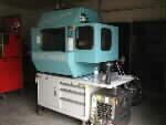
I also checked the power supply for the servos. It's that big honker transformer toroid and the choke toroid. I'm guessing that is the 70V supply and it appears there is a relay on the control PCA that will only switch on when it establishes communication with the computer. I didn't see any capacitors on the output unless they are on the control PCA and I need to pull the encoder PCA to see them. Otherwise, it seems they are directly fed to the servo control boards. That would make it easy to re-use. Just have to have a board to switch the AC input relay. Also will make it easy to ensure no movement until there is a stable system if I can have a control line from the computer energize (directly or indirectly) the relay.
Mac, you mentioned wiring the 70V supply. Is there something I am overlooking?
Checking voltages and making some diagrams I noticed I wrongly stated the 24V supply was locked out if there were insufficient air. That was incorrect. The 24V powers up regardless, the pressure switch signals the control PCA so I assume control originates from there.
I also checked the power supply for the servos. It's that big honker transformer toroid and the choke toroid. I'm guessing that is the 70V supply and it appears there is a relay on the control PCA that will only switch on when it establishes communication with the computer. I didn't see any capacitors on the output unless they are on the control PCA and I need to pull the encoder PCA to see them. Otherwise, it seems they are directly fed to the servo control boards. That would make it easy to re-use. Just have to have a board to switch the AC input relay. Also will make it easy to ensure no movement until there is a stable system if I can have a control line from the computer energize (directly or indirectly) the relay.
Mac, you mentioned wiring the 70V supply. Is there something I am overlooking?
Please Log in or Create an account to join the conversation.
- MacGalempsy
- Offline
- Senior Member
-
Less
More
- Posts: 68
- Thank you received: 2
01 Nov 2015 12:13 #64565
by MacGalempsy
Replied by MacGalempsy on topic Light Machine Corp. Benchman XTr (retrofit)
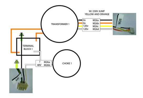
Here is the schematic I came up with for the High DC power loop. the M26 connector is the AC in and the M5 is the DC out. I ran the DC to a terminal block then connected them to each of the Amps. It works pretty well.
Please Log in or Create an account to join the conversation.
- MacGalempsy
- Offline
- Senior Member
-
Less
More
- Posts: 68
- Thank you received: 2
01 Nov 2015 12:18 #64566
by MacGalempsy
Replied by MacGalempsy on topic Light Machine Corp. Benchman XTr (retrofit)
dont forget a fuse between the DC out and the common terminal block!
Please Log in or Create an account to join the conversation.
- steve_a
- Offline
- Senior Member
-
Less
More
- Posts: 75
- Thank you received: 2
02 Nov 2015 10:12 - 02 Nov 2015 10:12 #64599
by steve_a
Replied by steve_a on topic Light Machine Corp. Benchman XTr (retrofit)
Thanks again Mac. Your research is fantastic!
Last edit: 02 Nov 2015 10:12 by steve_a. Reason: wrong attachment
Please Log in or Create an account to join the conversation.
- steve_a
- Offline
- Senior Member
-
Less
More
- Posts: 75
- Thank you received: 2
05 Nov 2015 12:52 - 05 Nov 2015 13:07 #64792
by steve_a
Replied by steve_a on topic Light Machine Corp. Benchman XTr (retrofit)
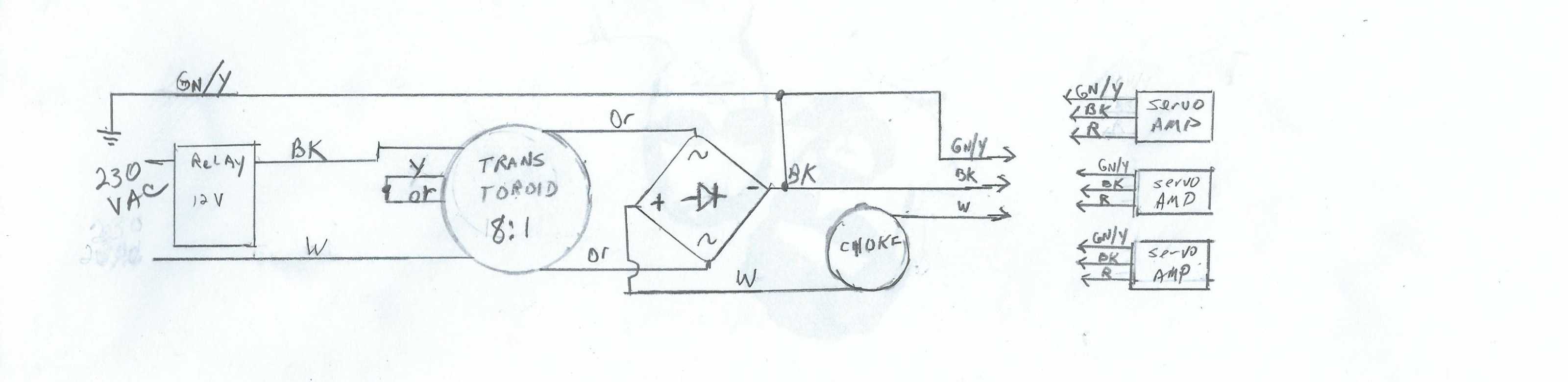
I have been working on preparations to do the controller swap and ordering a few parts I think I will need. While I was at it I decided to look closer at the drive supply. I did a quick ohm check of the BAT (Big A__ Toroid) and saw appox .8 ohm on both the input coils. I hadn't noticed before but there is only 1 output coil. ( I can only assume that is because this is a custom built toroid specifically for Light Machines and they designed it specifically for this machine.) The output showed about .2 ohms. Since the two .8 input coils are tied in series that makes an equivalent 1.6ohm coil making the input to output ratio 1.6/2 or 8:1. That gives 230V/8 = 28.75 V out. That seemed really small to me so I looked at the motors.
It turns out that My Z axis motor is a Moog C23-L50W20M09 and I believe the X and Y are the same. I looked at the Copley Controller information and noticed there are components added to match the motor to the controller. Page 5 shows what the components do and what values are needed. I found the RH15 resistor and determined it's values to be 402K which matches with model 4122 controller for a 1.8 to 4.8 mH Armature Inductance. Next I referenced the C23 series Motor specs. www.moog.com/literature/MCG/moc23series.pdf from Moog. The Motor shows an inductance of 1.96 Mh, in the correct range so I'm sure this is all set up correctly.
OK the reason I think all this is important is because I was wondering why the BAT looks like it will only source a calculated 28.75V. The motor specs shows that his motor is tolerant from 12-60V and rated for 24V. That seems to confirm my ohm measurements. Additionally, the Copley Controller operates from 22V to 90V.
So things are pointing to a 24V system. At least that's MY model with a 5000RPM spindle. Here's what I believe the drive supply looks like. (OOPS! wrong ratio... should be 8:1... I'll redraw and resubmit.)
I'm still waiting for my MESA controller so I am a bit stuck for now... I guess I could bypass the enable relay and see if I get 24V. Otherwise, I'm kind of at a standstill for now but I guess I need to find a relay board SO I think I will work on that.
Last edit: 05 Nov 2015 13:07 by steve_a. Reason: wrong attachment
Please Log in or Create an account to join the conversation.
Time to create page: 0.456 seconds