DMM DYN 4 servos + Mesa 5i25 & 7i77 XYZ+A Cnc 5x10
- ROB-CNC
- Offline
- New Member
-

Less
More
- Posts: 19
- Thank you received: 0
28 May 2015 23:53 - 17 Mar 2016 18:01 #59158
by ROB-CNC
Replied by ROB-CNC on topic DMM DYN 4 servos + Mesa 5i25 & 7i77 XYZ+A Cnc 5x10
Really appreciate all your help Alan!
That makes sense. I will wire it to ground and hope this does the trick.
Will get back in a few.
Thanks.
That makes sense. I will wire it to ground and hope this does the trick.
Will get back in a few.
Thanks.
Last edit: 17 Mar 2016 18:01 by ROB-CNC.
Please Log in or Create an account to join the conversation.
- alan_3301
- Offline
- Premium Member
-

Less
More
- Posts: 136
- Thank you received: 22
28 May 2015 23:56 #59159
by alan_3301
Replied by alan_3301 on topic DMM DYN 4 servos + Mesa 5i25 & 7i77 XYZ+A Cnc 5x10
make sure you read what PCW posted about the flyback diode and maximum coil current for the relay.
I'd hate for you to damage your board.
I'd hate for you to damage your board.
Please Log in or Create an account to join the conversation.
- ROB-CNC
- Offline
- New Member
-
Less
More
- Posts: 19
- Thank you received: 0
29 May 2015 00:07 #59160
by ROB-CNC
Replied by ROB-CNC on topic DMM DYN 4 servos + Mesa 5i25 & 7i77 XYZ+A Cnc 5x10
Thanks for the heads up, I read his post... I am currently manually activating the coil on and off, as this was exactly what I was afraid of getting wrong and damaging the board.
Please Log in or Create an account to join the conversation.
- ROB-CNC
- Offline
- New Member
-
Less
More
- Posts: 19
- Thank you received: 0
29 May 2015 03:07 - 17 Mar 2016 17:57 #59169
by ROB-CNC
Replied by ROB-CNC on topic DMM DYN 4 servos + Mesa 5i25 & 7i77 XYZ+A Cnc 5x10
I've tried wiring as suggest and the drives are not disabling... I'm all out of ideas. Not sure what I am doing wrong.
I have contacted DMM and I will see if they can send me some better wiring diagrams and proper explanation.
I'll find out when I get a reply from them.
I have contacted DMM and I will see if they can send me some better wiring diagrams and proper explanation.
I'll find out when I get a reply from them.
Last edit: 17 Mar 2016 17:57 by ROB-CNC.
Please Log in or Create an account to join the conversation.
- ROB-CNC
- Offline
- New Member
-
Less
More
- Posts: 19
- Thank you received: 0
29 May 2015 05:49 - 17 Mar 2016 17:55 #59176
by ROB-CNC
Replied by ROB-CNC on topic DMM DYN 4 servos + Mesa 5i25 & 7i77 XYZ+A Cnc 5x10
I probably have reread the manual a hundred times and I think I may have found a hint of why the drives are not disabling and responding to the analog command outputs from the controller when it should be disabled.
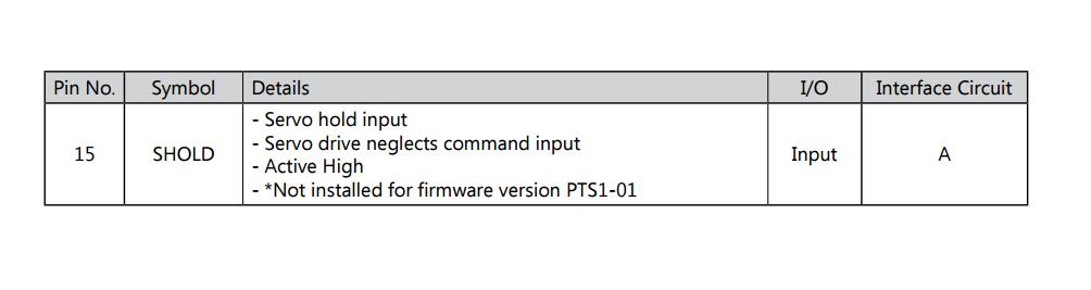
JP4 Pin 15 SHOLD disables the position command inputs. Pin 15 is required for my drive for enable/disable.
JP4 Pin 15 SHOLD disables the position command inputs. Pin 15 is required for my drive for enable/disable.
Last edit: 17 Mar 2016 17:55 by ROB-CNC.
Please Log in or Create an account to join the conversation.
- ROB-CNC
- Offline
- New Member
-
Less
More
- Posts: 19
- Thank you received: 0
02 Jun 2015 06:52 - 17 Mar 2016 17:49 #59323
by ROB-CNC
Replied by ROB-CNC on topic DMM DYN 4 servos + Mesa 5i25 & 7i77 XYZ+A Cnc 5x10
Seems like we figured this one out... Tested pin 15 as a enable pin and that surely did the trick.
DMM tech support confirmed this in a email (Thank you Aidin at DMM for clearing things up).
I'm posting the email reply on here as It may help any future Dyn4 users get going and set up quicker.
" Hi Robert,
It took us a while but we figured out it is a small change in the firmware for the drives for the Disable. There was a new firmware for the DYN4 drives released earlier last month that had the disable pin incorrectly set to Pin. 15 instead of Pin. 3. Pin. 3 is the pin outlined in the manual and initial requirement, but it was temporarily changed to Pin. 15 to test for develop I/O and was left there by mistake. So currently on the drives, Pin. 15 is the disable and Pin. 3 is not connected NC. This firmware was incorrectly migrated to our production QC software so it wasn't picked up at production.
So basically to disable the drive (using internal power) you will need to connect:
(1) Pin. 17 to Pin. 4 (provide +14V power)
(2) Pin. 15 to Pin. 1 (to activate disable to disable servo loop and motor shaft open)
Or using an external +24VDC power supply: connect positive terminal to Pin16 and connect Pin15 to the relay or negative terminal of your power supply.
Please note that this process will disable the servo loop and once the servo is in disable state the drive will ignore all input movement commands and the motor shaft will be FREE. If your requirements is to not allow any servo movement to be made, you should simply not input any command and the motor shaft will be LOCKED in normal servo operation!
Please let me know what you think.
Regards,
Aidin "
A few steps closer to finishing the machine.")
DMM tech support confirmed this in a email (Thank you Aidin at DMM for clearing things up).
I'm posting the email reply on here as It may help any future Dyn4 users get going and set up quicker.
" Hi Robert,
It took us a while but we figured out it is a small change in the firmware for the drives for the Disable. There was a new firmware for the DYN4 drives released earlier last month that had the disable pin incorrectly set to Pin. 15 instead of Pin. 3. Pin. 3 is the pin outlined in the manual and initial requirement, but it was temporarily changed to Pin. 15 to test for develop I/O and was left there by mistake. So currently on the drives, Pin. 15 is the disable and Pin. 3 is not connected NC. This firmware was incorrectly migrated to our production QC software so it wasn't picked up at production.
So basically to disable the drive (using internal power) you will need to connect:
(1) Pin. 17 to Pin. 4 (provide +14V power)
(2) Pin. 15 to Pin. 1 (to activate disable to disable servo loop and motor shaft open)
Or using an external +24VDC power supply: connect positive terminal to Pin16 and connect Pin15 to the relay or negative terminal of your power supply.
Please note that this process will disable the servo loop and once the servo is in disable state the drive will ignore all input movement commands and the motor shaft will be FREE. If your requirements is to not allow any servo movement to be made, you should simply not input any command and the motor shaft will be LOCKED in normal servo operation!
Please let me know what you think.
Regards,
Aidin "
A few steps closer to finishing the machine.
Last edit: 17 Mar 2016 17:49 by ROB-CNC.
Please Log in or Create an account to join the conversation.
- bevins
-
- Offline
- Platinum Member
-

Less
More
- Posts: 1942
- Thank you received: 338
29 Nov 2016 11:33 #83424
by bevins
This is backwards. I am in the process of purchasing servo and drives, and was looking at dmm-tech with these drives and servos.
I spoke with them and they still have not corrected this in the firmware as they think it is correct. I wont be purchasing these drives and servos.
Basically you have to make sure you power the enable pin before machine starts upon power up or they can move. I dont understand why they think this is correct. It would be easy to just swap the input in firmware or in parameters, and if you cannot do that i wont be buying these drives.
Replied by bevins on topic DMM DYN 4 servos + Mesa 5i25 & 7i77 XYZ+A Cnc 5x10
Seems like we figured this one out... Tested pin 15 as a enable pin and that surely did the trick.
DMM tech support confirmed this in a email (Thank you Aidin at DMM for clearing things up).
I'm posting the email reply on here as It may help any future Dyn4 users get going and set up quicker.
" Hi Robert,
It took us a while but we figured out it is a small change in the firmware for the drives for the Disable. There was a new firmware for the DYN4 drives released earlier last month that had the disable pin incorrectly set to Pin. 15 instead of Pin. 3. Pin. 3 is the pin outlined in the manual and initial requirement, but it was temporarily changed to Pin. 15 to test for develop I/O and was left there by mistake. So currently on the drives, Pin. 15 is the disable and Pin. 3 is not connected NC. This firmware was incorrectly migrated to our production QC software so it wasn't picked up at production.
So basically to disable the drive (using internal power) you will need to connect:
(1) Pin. 17 to Pin. 4 (provide +14V power)
(2) Pin. 15 to Pin. 1 (to activate disable to disable servo loop and motor shaft open)
Or using an external +24VDC power supply: connect positive terminal to Pin16 and connect Pin15 to the relay or negative terminal of your power supply.
Please note that this process will disable the servo loop and once the servo is in disable state the drive will ignore all input movement commands and the motor shaft will be FREE. If your requirements is to not allow any servo movement to be made, you should simply not input any command and the motor shaft will be LOCKED in normal servo operation!
Please let me know what you think.
Regards,
Aidin "
A few steps closer to finishing the machine.
This is backwards. I am in the process of purchasing servo and drives, and was looking at dmm-tech with these drives and servos.
I spoke with them and they still have not corrected this in the firmware as they think it is correct. I wont be purchasing these drives and servos.
Basically you have to make sure you power the enable pin before machine starts upon power up or they can move. I dont understand why they think this is correct. It would be easy to just swap the input in firmware or in parameters, and if you cannot do that i wont be buying these drives.
Please Log in or Create an account to join the conversation.
- bevins
-
- Offline
- Platinum Member
-
Less
More
- Posts: 1942
- Thank you received: 338
01 Feb 2017 15:01 #87124
by bevins
Replied by bevins on topic DMM DYN 4 servos + Mesa 5i25 & 7i77 XYZ+A Cnc 5x10
Did you ever get these DYN4's running? Can you show how you connected it in the end?
Please Log in or Create an account to join the conversation.
- ROB-CNC
- Offline
- New Member
-
Less
More
- Posts: 19
- Thank you received: 0
03 Feb 2017 17:32 - 03 Feb 2017 17:46 #87234
by ROB-CNC
Replied by ROB-CNC on topic DMM DYN 4 servos + Mesa 5i25 & 7i77 XYZ+A Cnc 5x10
Hello Bevins, sorry for the late reply... work keeps me very busy lately.
To answer your question, Yes, I did manage to get the Dyn4 to work reasonably well with the 7I77. I am running them in torque mode, +-10v analog. I am not completely happy with the way they tune but I managed to get them tuned enough to where I can run programs. The drives have very limited and unconventional tuning parameters. On my system the only way to get a decent tune was in torque mode which requires a lot of filtering and dampening but the filter and tuning parameters in the drive did not seem to work for me at all running in torque mode so I could only tune in LinuxCNC. Also, using the torq const. filter in the drive would create runaways for whatever reason. Maybe in step and dir they run better but I would need to swap my board out with a 7I76 to test. I'm just going to stick with the 7I77 and try to work on the tune some more when I get a chance.
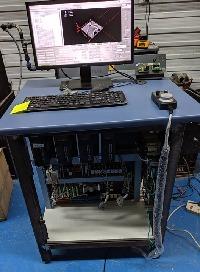
I drew some simplified sketches of how I wired the I/O from Dyn4 to 7I77. Now my control cabinet is a lot more complicated than the sketches and I have a electrical cad file with all the wiring, it can be a bit overwhelming. It would take a few hours to go through and study all the circuits. But hopefully the simplified sketches help you understand how I have it running.
The enable circuit (which is technically a disable in the Dyn4) required me to use a N/C relay to get this circuit working with the 7I77 since the Dyn4 enable(disable) logic is backwards. I run 24Vdc from the main logic PSU (Omron S82K-10024) to Dyn4 JP4 Pin 16, run pin 15 through a N/C relay to the PSU common. 7I77 triggers the coil which will enable drives when LinuxCNC is up and running. In my complete cabinet circuit I also run a PILZ safety relay tied to my main estop which keeps the drives from powering on till I am booted into LinuxCNC it also keeps me from powering on the drives when no 24vdc "disable" signal present or if there's any sort of fault. I don't have to worry about runaways happening before linuxCNC takes over and the control system is ready. I don't show the safety loop in thw simplified sketch but it shouldn't be too hard to implement in your system. Professional CNC cabinets should always have a good safety relay anyways to handle estops, failures and such.
I can, if needed, draw some simplified sketches of how my high voltage side is wired and how the main contractors power on sequence is setup.
Let me know if this is of any help.
Robert
To answer your question, Yes, I did manage to get the Dyn4 to work reasonably well with the 7I77. I am running them in torque mode, +-10v analog. I am not completely happy with the way they tune but I managed to get them tuned enough to where I can run programs. The drives have very limited and unconventional tuning parameters. On my system the only way to get a decent tune was in torque mode which requires a lot of filtering and dampening but the filter and tuning parameters in the drive did not seem to work for me at all running in torque mode so I could only tune in LinuxCNC. Also, using the torq const. filter in the drive would create runaways for whatever reason. Maybe in step and dir they run better but I would need to swap my board out with a 7I76 to test. I'm just going to stick with the 7I77 and try to work on the tune some more when I get a chance.
I drew some simplified sketches of how I wired the I/O from Dyn4 to 7I77. Now my control cabinet is a lot more complicated than the sketches and I have a electrical cad file with all the wiring, it can be a bit overwhelming. It would take a few hours to go through and study all the circuits. But hopefully the simplified sketches help you understand how I have it running.
The enable circuit (which is technically a disable in the Dyn4) required me to use a N/C relay to get this circuit working with the 7I77 since the Dyn4 enable(disable) logic is backwards. I run 24Vdc from the main logic PSU (Omron S82K-10024) to Dyn4 JP4 Pin 16, run pin 15 through a N/C relay to the PSU common. 7I77 triggers the coil which will enable drives when LinuxCNC is up and running. In my complete cabinet circuit I also run a PILZ safety relay tied to my main estop which keeps the drives from powering on till I am booted into LinuxCNC it also keeps me from powering on the drives when no 24vdc "disable" signal present or if there's any sort of fault. I don't have to worry about runaways happening before linuxCNC takes over and the control system is ready. I don't show the safety loop in thw simplified sketch but it shouldn't be too hard to implement in your system. Professional CNC cabinets should always have a good safety relay anyways to handle estops, failures and such.
I can, if needed, draw some simplified sketches of how my high voltage side is wired and how the main contractors power on sequence is setup.
Let me know if this is of any help.
Robert
Last edit: 03 Feb 2017 17:46 by ROB-CNC.
Please Log in or Create an account to join the conversation.
- Todd Zuercher
-

- Offline
- Platinum Member
-
Less
More
- Posts: 4747
- Thank you received: 1454
03 Feb 2017 18:16 #87239
by Todd Zuercher
Replied by Todd Zuercher on topic DMM DYN 4 servos + Mesa 5i25 & 7i77 XYZ+A Cnc 5x10
Any idea why you were not able to make them work for you in velocity(speed) mode?
For tuning a torque mode servo, I've had decent luck running two PID loops in linuxcnc. An ordinary position loop running in the servo-thread sends the velocity command to another PID running in a floating point base-thread running about 5khz sends the torque command to the drive. (Don't forget you need to read/write your Mesa hardware in the base-thread for this to work.)
For tuning a torque mode servo, I've had decent luck running two PID loops in linuxcnc. An ordinary position loop running in the servo-thread sends the velocity command to another PID running in a floating point base-thread running about 5khz sends the torque command to the drive. (Don't forget you need to read/write your Mesa hardware in the base-thread for this to work.)
The following user(s) said Thank You: new2linux
Please Log in or Create an account to join the conversation.
Time to create page: 0.159 seconds