I had this crazy idea - Lets build a shock dyno with Linuxcnc
- rodw
-
 Topic Author
- Offline
- Platinum Member
-

Less
More
- Posts: 11986
- Thank you received: 4083
10 Jan 2020 04:12 #154525
by rodw
Replied by rodw on topic I had this crazy idea - Lets build a shock dyno with Linuxcnc
So now have this clear in my head. Here is a couple of photos of a shaper and a CAD design for one courtesy of my mate Chris..
This one uses a bolt in a slot as Andy proposed, nice and easy.

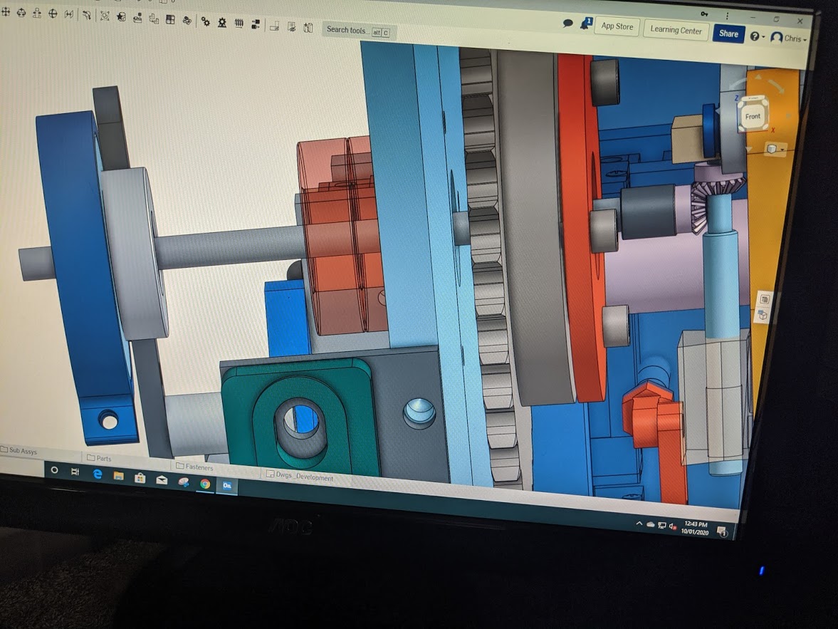
And here is Chris's CAD design in OnShape using bevel gears to adjust the stroke with some parts supressed.
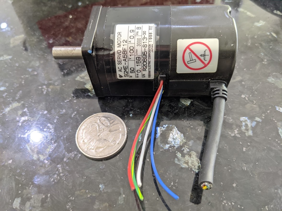
And the little servo I have that is looking for something to do... Aussie 20c piece for size reference.
This is very cool to watch the animation running.
This one uses a bolt in a slot as Andy proposed, nice and easy.
And here is Chris's CAD design in OnShape using bevel gears to adjust the stroke with some parts supressed.
And the little servo I have that is looking for something to do... Aussie 20c piece for size reference.
This is very cool to watch the animation running.
Attachments:
Please Log in or Create an account to join the conversation.
- andypugh
-

- Offline
- Moderator
-

Less
More
- Posts: 19875
- Thank you received: 4642
10 Jan 2020 11:14 #154537
by andypugh
Replied by andypugh on topic I had this crazy idea - Lets build a shock dyno with Linuxcnc
That's a slightly atypical shaper. Bigger ones have a handle that allows you to adjust the stroke while the machine is running (though the handle typically rotates, and the operator has the job of turning the handle faster or slower than the "natural" speed to adjust the stroke. Which is pretty much what the servo needs to do, but using encoders.
I have had a think on the way in to work today, I think you can retain the crank-on-motor design and still have CNC stroke adjustment.
Watch this space")
I have had a think on the way in to work today, I think you can retain the crank-on-motor design and still have CNC stroke adjustment.
Watch this space
Please Log in or Create an account to join the conversation.
- rodw
-
Topic Author
- Offline
- Platinum Member
-
Less
More
- Posts: 11986
- Thank you received: 4083
10 Jan 2020 11:45 #154539
by rodw
Replied by rodw on topic I had this crazy idea - Lets build a shock dyno with Linuxcnc
Remembering this was a crazy idea and is getting crazier, I was even wondering if you couldn't run a linear stage and get power to it via a slip ring www.aliexpress.com/item/32847470025.html...0.0.0.444d2e0etaJER7
This one has 12 wires so 2 wires to each stepper terminal for current handling would allow 4 wires for home and limit switches (but you'd really only need a single shared home/limit switch.
This one is metal and rated to 1000 RPM but I found some other plastic 6 wire ones with thicker rated for up to 800 RPM
Please Log in or Create an account to join the conversation.
- andypugh
-
- Offline
- Moderator
-
Less
More
- Posts: 19875
- Thank you received: 4642
10 Jan 2020 11:59 #154540
by andypugh
To move during action I do think that a pair of linear slides and a ball screw is the way to go.
But, rather than use a many-way slip ring you could use a 2-way high-current slip-ring, an integrated stepper with built-in driver and some sort of wireless protocol to control it.
Replied by andypugh on topic I had this crazy idea - Lets build a shock dyno with Linuxcnc
Remembering this was a crazy idea and is getting crazier, I was even wondering if you couldn't run a linear stage and get power to it via a slip ring
To move during action I do think that a pair of linear slides and a ball screw is the way to go.
But, rather than use a many-way slip ring you could use a 2-way high-current slip-ring, an integrated stepper with built-in driver and some sort of wireless protocol to control it.
Please Log in or Create an account to join the conversation.
- rodw
-
Topic Author
- Offline
- Platinum Member
-
Less
More
- Posts: 11986
- Thank you received: 4083
10 Jan 2020 12:36 #154542
by rodw
Replied by rodw on topic I had this crazy idea - Lets build a shock dyno with Linuxcnc
Andy, you are crazier than I am!
There were some 6 wire ones with thicker wires (5 amps they said), good for 800 rpm. I'll look a bit more. Simple is good but a couple of zigbees maybe? Just send Gcode to a Grbl controller.
Next thing you'll want to be using an AC servo with mutiplexed step and direction signals somehow.
BUt if the stepper was under Linuxcnc control, life would be easier as it could be calibrated as if it was just another axis.
Please Log in or Create an account to join the conversation.
- andypugh
-
- Offline
- Moderator
-
Less
More
- Posts: 19875
- Thank you received: 4642
10 Jan 2020 12:47 - 10 Jan 2020 12:48 #154544
by andypugh
With a custom brushless motor this sort of thing gets quite easy...
photos.app.goo.gl/LJ6W4rXKeF4Lnw3g6
What this is is a custom brushless motor with a very large through-bore. The field windings are static in the middle wrapped round the tool shaft. An outrunner with the magnets operates the boring head.
This is very similar to what is being discussed here.
With a large and flat one of these around your motor shaft... www.kollmorgen.com/en-us/developer-network/kbm-motor/
(... You could spend a great deal of money)
Replied by andypugh on topic I had this crazy idea - Lets build a shock dyno with Linuxcnc
Next thing you'll want to be using an AC servo with mutiplexed step and direction signals somehow
With a custom brushless motor this sort of thing gets quite easy...
photos.app.goo.gl/LJ6W4rXKeF4Lnw3g6
What this is is a custom brushless motor with a very large through-bore. The field windings are static in the middle wrapped round the tool shaft. An outrunner with the magnets operates the boring head.
This is very similar to what is being discussed here.
With a large and flat one of these around your motor shaft... www.kollmorgen.com/en-us/developer-network/kbm-motor/
(... You could spend a great deal of money)
Last edit: 10 Jan 2020 12:48 by andypugh.
Please Log in or Create an account to join the conversation.
- rodw
-
Topic Author
- Offline
- Platinum Member
-
Less
More
- Posts: 11986
- Thank you received: 4083
10 Jan 2020 13:18 #154545
by rodw
Replied by rodw on topic I had this crazy idea - Lets build a shock dyno with Linuxcnc
I think I've found a 6 wire 12 AWG one rated for 500 RPM. RPM is OK (800 would be better). The wires are big enough for the steppers and leaves 2 wires for a home switch. I think that is the way forward. I've got well over $1.5k in the motor and VFD so I have to use it now.
Do you think a NEMA 17 would have enough holding torque or would I need a NEMA 23?
Do you think a NEMA 17 would have enough holding torque or would I need a NEMA 23?
Please Log in or Create an account to join the conversation.
- andypugh
-
- Offline
- Moderator
-
Less
More
- Posts: 19875
- Thank you received: 4642
10 Jan 2020 13:25 #154547
by andypugh
Replied by andypugh on topic I had this crazy idea - Lets build a shock dyno with Linuxcnc
a360.co/2scAC2g
Bevel gear on the leadscrew (not shown) that moves a "big end" on a plate mounted to linear rails (not shown).
The mating bevel gear is carried on a bearing (possibly double row) pressed on to the taperlock hub.
A toothed belt drive (not shown) from the stroke adjust servo rotates the bevel gear.
But the bevels themselves look pretty costly:
www.hpcgears.com/pdf_c33/14.16-14.22.pdf
Bevel gear on the leadscrew (not shown) that moves a "big end" on a plate mounted to linear rails (not shown).
The mating bevel gear is carried on a bearing (possibly double row) pressed on to the taperlock hub.
A toothed belt drive (not shown
) from the stroke adjust servo rotates the bevel gear.But the bevels themselves look pretty costly:
www.hpcgears.com/pdf_c33/14.16-14.22.pdf
Please Log in or Create an account to join the conversation.
- rodw
-
Topic Author
- Offline
- Platinum Member
-
Less
More
- Posts: 11986
- Thank you received: 4083
10 Jan 2020 21:18 #154584
by rodw
Replied by rodw on topic I had this crazy idea - Lets build a shock dyno with Linuxcnc
Andy thanks. Took me ages to workout what you had done. After I dug in to your assembly I found a taper flange. 
Here is what the side profile of my flange looks like
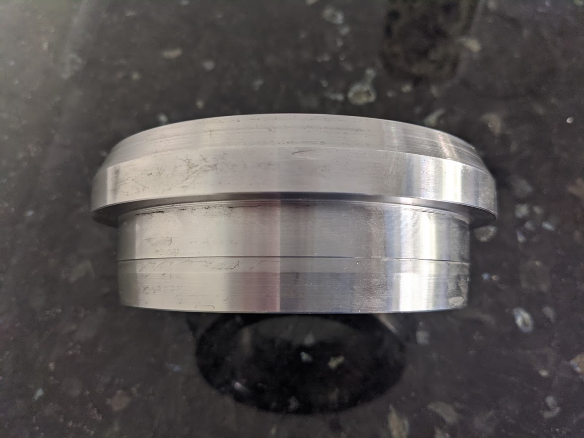
So welding a 16mm plate (with a hole in it) flush with the top face of the flange would be nice as there would be a groove for the weld.
The wide part of the flange is 20mm thick so it will protrude on the rear (motor side) 4mm and there is a 12mm parallel section to press your bearing assembly too. I think it needs to carry an encoder for the motor too so it might be a big bevel gear.
Pretty sure I could source them from Ronson Gears heare in Aus.
There will be about 35mm of room behind the flange so there is plenty of room.
Here is what the side profile of my flange looks like
So welding a 16mm plate (with a hole in it) flush with the top face of the flange would be nice as there would be a groove for the weld.
The wide part of the flange is 20mm thick so it will protrude on the rear (motor side) 4mm and there is a 12mm parallel section to press your bearing assembly too. I think it needs to carry an encoder for the motor too so it might be a big bevel gear.
Pretty sure I could source them from Ronson Gears heare in Aus.
There will be about 35mm of room behind the flange so there is plenty of room.
Please Log in or Create an account to join the conversation.
- andypugh
-
- Offline
- Moderator
-
Less
More
- Posts: 19875
- Thank you received: 4642
15 Jan 2020 19:01 #154945
by andypugh
Replied by andypugh on topic I had this crazy idea - Lets build a shock dyno with Linuxcnc
Here is a way to do variable-stroke all mechanically:
www.practicalmachinist.com/vb/general/hb...3472260/#post3472260
The electronic way is much simpler.
www.practicalmachinist.com/vb/general/hb...3472260/#post3472260
The electronic way is much simpler.
The following user(s) said Thank You: rodw
Please Log in or Create an account to join the conversation.
Time to create page: 0.396 seconds