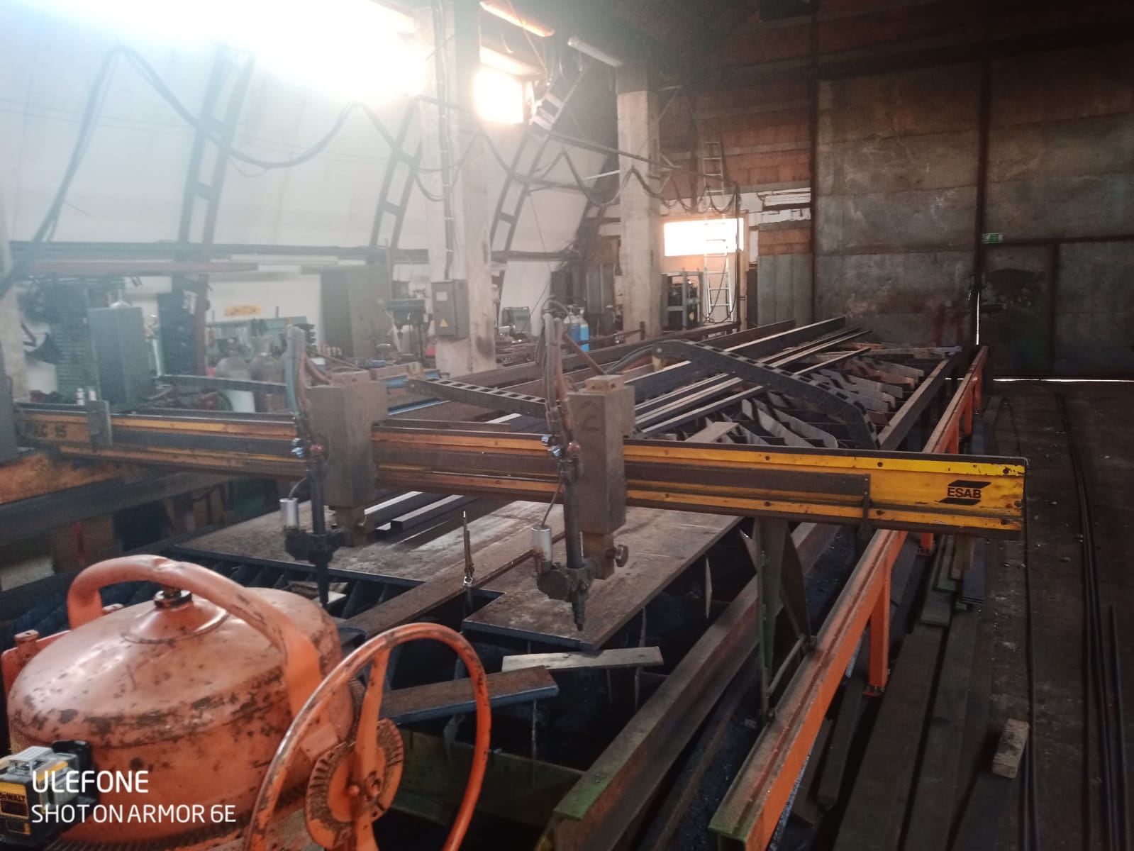
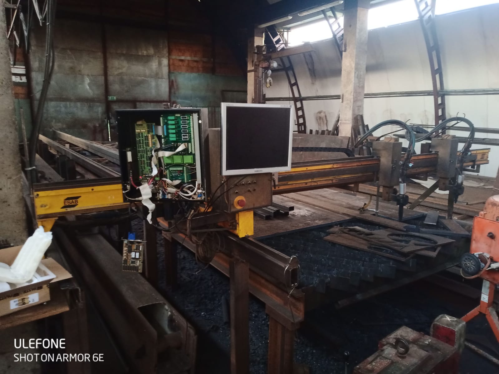
RETROFIT Oxy Acetylene 3 HEAD CNC
- FooBar
-
 Topic Author
- Offline
- New Member
-

- Posts: 2
- Thank you received: 1
HELLO
I want to retrofit Oxy Acetylene 3 HEAD CNC.
Wich has:
X-axis with 2 parallel moving motor.
y-1 axis
y-2 axis
y-3 axis
z-1 axis
z-2 axis
z-3 axis
Parts to use:
CONTROLLER:
MESA 6I24-16 FPGA based PCI Anything I/O card
eusurplus.com/index.php?route=product/pr..._62_70&product_id=78
MESA THCAD-300 High isolation A-D accessory
eusurplus.com/index.php?route=product/pr..._61_67&product_id=53
MOTORS:
To use step and direct motors like this or something similar.
www.omc-stepperonline.com/Integrated-Ste...op.html?search=servo
50 pin daughter cards
eusurplus.com/index.php?route=product/category&path=59_61_73
Basic machine operation.
At the moment most of the time we use one head only the other head is manually put it at the side or it stays where we want the motor is turned off.
Some times the second head is in parallel operation to duplicate parts.
3 head is unused.
We want to add to the 3 head a plasma cutter.
My question is?
Is it possible to config LinuxCNC into two operation modes? Cutting with Oxy-Acetylene Or with Plasma cutter like MODE1 MODE2?
And how to conf 8 motors in LinuxCNC?
And how should the machine operate 3 heads when I choose different operation modes.
And how the should be done the parallel cutting with 2 head Oxy-Acetylene?
Any ideas are great
Thanks for listening.
Please Log in or Create an account to join the conversation.
- tommylight
-

- Away
- Moderator
-

- Posts: 21240
- Thank you received: 7251
Please Log in or Create an account to join the conversation.
- Aciera
-

- Offline
- Administrator
-

- Posts: 4650
- Thank you received: 2070
If you are ok with closing one config and opening another then that should not be difficult. If you want to do it inside a program then it will get more challenging.Is it possible to config LinuxCNC into two operation modes? Cutting with Oxy-Acetylene Or with Plasma cutter like MODE1 MODE2?
LinuxCNC can drive 9 motors independently.And how to conf 8 motors in LinuxCNC?
I guess you could try to set up a config with y2 being a slave axis to y1 just like you will have x2 as a slave axis to x1 but I don't have any experience with slave axis. So I'm not sure if it is possible to define an offset between the two.And how the should be done the parallel cutting with 2 head Oxy-Acetylene?
Or you could configure the y2 as v axis. Then you could move y1 (y axis) independently from y2 (v axis) but your gcode will have to deal with the v axis.
Or maybe you could go all fancy and create a new kinematic where you could add an offset between y1 and y2 from the GUI and the v axis will get the positional commands from the y axis plus the offset. But this would be fairly involved as it would require to alter the kinematics file written in C and rebuild LinuxCNC.
So many things are possible. Which you choose largely depends on your abilities with programming and/or willingness to master the system.
Please Log in or Create an account to join the conversation.
- FooBar
-
 Topic Author
- Offline
- New Member
-

- Posts: 2
- Thank you received: 1
Please Log in or Create an account to join the conversation.
- Todd Zuercher
-

- Offline
- Platinum Member
-

- Posts: 4696
- Thank you received: 1439
I've retrofitted some multi head routers to Linuxcnc that are configured similarly, but without the ability to adjust the distance between the routers.
For starters, use Linuxcnc version 2.8 or newer. The joint-axis clarification in those newer versions will make setting up this machine easier. (2.8 is technically still pre-release but for all intents and purposes it is ready for public consumption.)
X1, and X2 are easy, this is simply a standard gantry configuration. Follow examples given for gantry machines for these joints.
For the 3 Y-axis joints. You need to decide how you'd like to use them. If you want to use them only for making duplicate parts, with potentially using all 3 at the same time, I think I would slave them together as a single Y-axis, with a secondary axis letter or letters specifying the distance between each one. So a G1V500 command would move either one or all the Y-joints 500mm apart. Then a Y commands would move all of the Y-joints the same distance in parallel motion.
Finally for the Z axis. For my machines I normally have each parallel Z axis configured with their own axis letter, Z,W,U,V. That is fine if you only have 4, but what if you need more? This also ran afoul of the new trajectory planner if you need more than 1 line of look ahead such as for a 3-D wood carving machine. So I worked out a way to temporarily slave and unslave the joints of the U,V,W axis to the Z axis using custom M -codes. This let me easily control and set different offsets for each of these joints. It also removed the need to assign an axis letter to each of these parallel Z axis joints. I did this all with some complex hal trickery. The addition of external offsets to Linuxcnc kind of does some of the same things I was doing but with fewer hal complexities, I've played with using it instead in a simulation but have not implemented it or a Joint/Axis configuration on a machine yet.
The temporary joint slaving/unslaving idea could also be implemented for your 3rd Y joint if you want to treat it as an independent Y-axis. Where Y1 and Y2 are two slaves with V being the offset between them and Y3 is normally parked off to the side and unused. then when you switch Y1 and 2 are moved together, and parked to the side and Y3 and Z3 becomes the commanded Y and Z axis.
Working out the details of how soft-limits are handled might be the most difficult task. It might be simpler just to ignore them and only rely on hard limit switches, but what's the fun in that. Crash prediction is something you shouldn't have to give up.
Please Log in or Create an account to join the conversation.
- Aciera
-

- Offline
- Administrator
-

- Posts: 4650
- Thank you received: 2070
I'm particularily interested in this. Is this something that is built in or have you created this yourself?G1V500 command would move either one or all the Y-joints 500mm apart. Then a Y commands would move all of the Y-joints the same distance in parallel motion.
Please Log in or Create an account to join the conversation.
- Todd Zuercher
-

- Offline
- Platinum Member
-

- Posts: 4696
- Thank you received: 1439
I am not a programer, and writing C components is a little out of my league. This is cobbled together using "standard" Linuxcnc stuff from Linuxcnc v2.7. Because of the complexities of the Hal file it may not import well into Linuxcnc v.2.8. I can easily see the auto conversion script choking on it.
Here is the parallel port config so you don't have to hunt for it.
Attachments:
Please Log in or Create an account to join the conversation.
- Aciera
-

- Offline
- Administrator
-

- Posts: 4650
- Thank you received: 2070
Just as possible route to deal with the soft-limits:Working out the details of how soft-limits are handled might be the most difficult task
You can actually change the soft limits set in the INI, even during gcode execution.
To do this there has to be a forced sync by issuing M66 E0 L0 then set a motion.digital-out-0N that is connected to the mux.limit_n_x and another M66 E0 L0
In my application I switch kinematics. In trivkins I use the limits for x and z as set in the INI file in nontrivial kinematics I set those to a value of 999999 (But that of course could be any number) So I use motion.analog-out-03 to set kinstype to 1 and then tie that to the selector pin of the mux (disregard the OFFSET_SEL_PIN as that is used for something else) :
;M429 by remap: select modified xyzbc kins
o<429remap>sub
  #<SWITCHKINS_PIN> = 3  ; set N as required: motion.analog-out-0N
  #<OFFSET_SEL_PIN> = 3  ; set N as required: motion.digital-out-0N
  #<kinstype> = 1        ; modified xyzbc kins

o1 if [exists [#<_hal[motion.switchkins-type]>]]
o1 else
     (debug,M429:Missing [RS274NGC]FEATURE==8)
     (debug,STOP)
     M2
o1 endif

   M66  E0 L0                           ; force synch
   M64  P#<OFFSET_SEL_PIN> 	        ; set XYZBC x- and z-offset to current position
   M68  E#<SWITCHKINS_PIN> Q#<kinstype> ; set kinstype value
   M65  P#<OFFSET_SEL_PIN> 	        ; reset x-z-offset pin to 0
   M66  E0 L0                           ; force synch
;   (debug, M429:modified xyzbc kins)

o2 if [[#<_task> EQ 1] AND [#<_hal[motion.switchkins-type]> NE 1]]
     (debug,M429:Wrong motion.switchkins-type)
     (debug,or missing hal net to analog-out-0x)
     (debug,STOP)
     M2
o2 else
o2 endif

o<429remap>endsub
# ---switch limits x_pos and z_neg between kinematics---
# ! ini.x.max_limit and ini.z.min_limit are then set in "custom_postgui.hal !
net kinematic-nontriv <= kinstype.is-1 => not.kins.in
net kinematic-triv <= not.kins.out
setp mux.limit_x_pos.in0 [AXIS_X]MAX_LIMIT
setp mux.limit_x_pos.in1 999999
net kinematic-nontriv => mux.limit_x_pos.sel => mux.limit_z_neg.sel
net limit-x-pos-set <= mux.limit_x_pos.out
setp mux.limit_z_neg.in0 [AXIS_Z]MIN_LIMIT
setp mux.limit_z_neg.in1 -999999
net limit-z-neg-set <= mux.limit_z_neg.outcustom_postgui.hal:
net limit-x-pos-set      <= mux.limit_x_pos.out   => ini.x.max_limit
net limit-z-neg-set      <= mux.limit_z_neg.out   => ini.z.min_limit
I hope this makes somewhat sense and somebody may find it useful.
Please Log in or Create an account to join the conversation.


