I am stuck with Biesse Rover 322 retrofit
- viesturs.lacis
- Offline
- Premium Member
-

Less
More
- Posts: 104
- Thank you received: 3
13 Nov 2020 12:05 #189200
by viesturs.lacis
I am stuck with Biesse Rover 322 retrofit was created by viesturs.lacis
Hello!
I guess I should start my own thread rather than highjack other threads with my questions.
I am in process of retrofitting Biesse Rover 322 to LinuxCNC. My biggest problem is total lack of documentation for this machine. Since I have already done another Biesse retrofit for these guys, I am using electric plans of that older Biesse to get at least some understanding of what is going on at the control cabinet. I have attached a picture of both of the machines - on the left is the old one that is now working, on the right there is the new one. Electric plans from old machine help to some degree as lots of things, wire numbers and relay names match. But not everything. Main change is that I/O blocks are now communicated through rs-485 compared to separate relays or optoisolators. Another new thing is the presence of TDX, TCEN and TSX safety circuit relays that I have no idea, how they operate. All the safety barriers around the machine have been removed before this machine was acquired so I will have to circumvent that as well.
I would like to start with getting the motors to move and then gradually move on with all the protection circuits that I have skipped.
What I have done so far:
1) I have made shortcut connection from A2 to A3 to bypass all the safety relays. That way I can engage KA relay. I believe that is main relay that enables the machine. Can somebody, please, confirm that?
As I engage KA relay, there is a small dot appearing on servodrive on second from the left "screen". The label on the drive says that it means "power". Does it mean that servodrive is enabled and should actually work?
2) I have connected servodrives to Mesa 7i48 board. In the electric plans of old machine I found a pinout of the connector at CNC controller end and it seemed to match this machine as well. At least encoder wires are good, so I would like to believe that analog outout should be there as well, but I have no idea, how to check for sure. I would appreciate any ideas on this matter.
I have also connected 3 outputs from servodrives to Mesa 7i37 inputs. When I engage KA relay, these inputs go from "true" to "false". I believe that these are "servo drive fault" or something similar.
In a parallel thread someone wrote that servodrives have "drive ready" output as well. I have not found it yet.
3) I have set up a test config, where I control analog outputs to servodrives with sliders in pyvcp panel. I have confirmed with multimeter that 7i48 board analog outputs do work. I get from 0 to 8 V reading. But none of the drives are working.
I do understand that Z axis has moved down, limit switch is engaged and the drive on the right, which is for Z motor, will not move in one direction. It still should move the opposite direction.
I would appreciate any tips on why none of the motors would move at least just a little...
Please Log in or Create an account to join the conversation.
- bevins
-
- Offline
- Platinum Member
-

Less
More
- Posts: 1942
- Thank you received: 338
13 Nov 2020 14:02 - 13 Nov 2020 14:04 #189203
by bevins
These are CACR Yaskawa drives. The . bb means they are ok and ready to be enabled. IT will show run when they are enabled. The POT is the axis in on limit switch.
They are probably in velocity mode so a 7i92/7i77 would work. Probably need more I/O.
I dont know what relays are in there if you have the rs485 modules or hardwire relays. If hardwire relays, you just have to remove the triggers from the control and the rest you can leave there. Hope I am being clear....
That's a great machine.
These are great drives. You can drive a truck over them. I left the green light circuit on mine and incorporated it into the estop circuit.
Let me now if you need more help. The green lite circuit is probably the same as my Biesse 346.
Got some pics of the cabinet , relays and control?
Replied by bevins on topic I am stuck with Biesse Rover 322 retrofit
Hello!
I guess I should start my own thread rather than highjack other threads with my questions.
I am in process of retrofitting Biesse Rover 322 to LinuxCNC. My biggest problem is total lack of documentation for this machine. Since I have already done another Biesse retrofit for these guys, I am using electric plans of that older Biesse to get at least some understanding of what is going on at the control cabinet. I have attached a picture of both of the machines - on the left is the old one that is now working, on the right there is the new one. Electric plans from old machine help to some degree as lots of things, wire numbers and relay names match. But not everything. Main change is that I/O blocks are now communicated through rs-485 compared to separate relays or optoisolators. Another new thing is the presence of TDX, TCEN and TSX safety circuit relays that I have no idea, how they operate. All the safety barriers around the machine have been removed before this machine was acquired so I will have to circumvent that as well.
I would like to start with getting the motors to move and then gradually move on with all the protection circuits that I have skipped.
What I have done so far:
1) I have made shortcut connection from A2 to A3 to bypass all the safety relays. That way I can engage KA relay. I believe that is main relay that enables the machine. Can somebody, please, confirm that?
As I engage KA relay, there is a small dot appearing on servodrive on second from the left "screen". The label on the drive says that it means "power". Does it mean that servodrive is enabled and should actually work?
2) I have connected servodrives to Mesa 7i48 board. In the electric plans of old machine I found a pinout of the connector at CNC controller end and it seemed to match this machine as well. At least encoder wires are good, so I would like to believe that analog outout should be there as well, but I have no idea, how to check for sure. I would appreciate any ideas on this matter.
I have also connected 3 outputs from servodrives to Mesa 7i37 inputs. When I engage KA relay, these inputs go from "true" to "false". I believe that these are "servo drive fault" or something similar.
In a parallel thread someone wrote that servodrives have "drive ready" output as well. I have not found it yet.
3) I have set up a test config, where I control analog outputs to servodrives with sliders in pyvcp panel. I have confirmed with multimeter that 7i48 board analog outputs do work. I get from 0 to 8 V reading. But none of the drives are working.
I do understand that Z axis has moved down, limit switch is engaged and the drive on the right, which is for Z motor, will not move in one direction. It still should move the opposite direction.
I would appreciate any tips on why none of the motors would move at least just a little...
These are CACR Yaskawa drives. The . bb means they are ok and ready to be enabled. IT will show run when they are enabled. The POT is the axis in on limit switch.
They are probably in velocity mode so a 7i92/7i77 would work. Probably need more I/O.
I dont know what relays are in there if you have the rs485 modules or hardwire relays. If hardwire relays, you just have to remove the triggers from the control and the rest you can leave there. Hope I am being clear....
That's a great machine.
These are great drives. You can drive a truck over them. I left the green light circuit on mine and incorporated it into the estop circuit.
Let me now if you need more help. The green lite circuit is probably the same as my Biesse 346.
Got some pics of the cabinet , relays and control?
Last edit: 13 Nov 2020 14:04 by bevins.
Please Log in or Create an account to join the conversation.
- bevins
-
- Offline
- Platinum Member
-
Less
More
- Posts: 1942
- Thank you received: 338
13 Nov 2020 14:12 #189204
by bevins
Replied by bevins on topic I am stuck with Biesse Rover 322 retrofit
I just reread your post. IF you have the rs485 relays then I would suggest removing them and put in Mesai/o and relays.
I have been down the road trying to get those rs485 modules to work to nopp avail. They have some high speed rs485 comms you will have to re-engineer. You can put some combination of 7i84/7i70, 7i71around the machine connected back to a 7i74.
That's what I did and it worked no issues easy to setup and it just works. I used 5i25 and 7i77, but you can use 7i92M instead of 5i25.
This is just my suggestions.
You have drill banks and two spindles? Will need a remap most likely.
Please Log in or Create an account to join the conversation.
- viesturs.lacis
- Offline
- Premium Member
-
Less
More
- Posts: 104
- Thank you received: 3
13 Nov 2020 14:17 - 13 Nov 2020 14:18 #189206
by viesturs.lacis
I moved the Z axis off the limit switch, all the drives now show bb. Thank you for the hint, I have not made it so far to get "run" on drives, so that means I still have not enabled them. That is good to know. The question remains - how do I enable them? What else is there in the circuit?
BTW I managed to find the manual for the servodrive: www.redrive.net/content/public/TSE-S800-11.1E.pdf
I am now going through it to see, which is enable input so that I can try to trace in the machine.
I am trying to keep the new setup as close as possible to the old machine - I have Mesa 5i24 in PC, 7i48 for servo control, 7i37TA for I/O in the cabinet (8 outputs should do, I had not noticed the 7i84 board, when I ordered, because putting both 7i70 AND 7i71 in cabinet for 15 inputs and 9 outputs seemed like an overkill) and then I have [7i44 in the control cabinet for] 7i70 and 7i71 to put on top of carriage to handle all the solenoids. I know that there are more I/O blocks under the machine in the middle and left side, but the client says that they will not use the original vacuum setup and tool change. I will not argue with them.
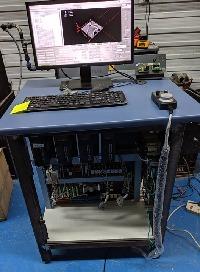
Attached is a picture of cabinet. Let me know, what particular things you are interested in.
Replied by viesturs.lacis on topic I am stuck with Biesse Rover 322 retrofit
These are CACR Yaskawa drives. The . bb means they are ok and ready to be enabled. IT will show run when they are enabled. The POT is the axis in on limit switch.
I moved the Z axis off the limit switch, all the drives now show bb. Thank you for the hint, I have not made it so far to get "run" on drives, so that means I still have not enabled them. That is good to know. The question remains - how do I enable them? What else is there in the circuit?
BTW I managed to find the manual for the servodrive: www.redrive.net/content/public/TSE-S800-11.1E.pdf
I am now going through it to see, which is enable input so that I can try to trace in the machine.
I am trying to keep the new setup as close as possible to the old machine - I have Mesa 5i24 in PC, 7i48 for servo control, 7i37TA for I/O in the cabinet (8 outputs should do, I had not noticed the 7i84 board, when I ordered, because putting both 7i70 AND 7i71 in cabinet for 15 inputs and 9 outputs seemed like an overkill) and then I have [7i44 in the control cabinet for] 7i70 and 7i71 to put on top of carriage to handle all the solenoids. I know that there are more I/O blocks under the machine in the middle and left side, but the client says that they will not use the original vacuum setup and tool change. I will not argue with them.
Attached is a picture of cabinet. Let me know, what particular things you are interested in.
Last edit: 13 Nov 2020 14:18 by viesturs.lacis.
Please Log in or Create an account to join the conversation.
- viesturs.lacis
- Offline
- Premium Member
-
Less
More
- Posts: 104
- Thank you received: 3
13 Nov 2020 14:33 - 13 Nov 2020 14:39 #189208
by viesturs.lacis
Yes, I found another forum where somebody wrote exactly the same conclusion - that RS-485 communication could not be cracked to get it to work with LinuxCNC as they are using some proprietary protocol. I guess that it is doable, but not for mere mortals like me.
I have 7i70 and 7i71 for all the solenoids for the drill blocks and all the other stuff that is on the carriage. The machine actually has 3 spindles, just like the old machine I did previously.
I am now reading through the manual of servo drive. I found a page, which describes I/O control signals. Attached are 2 screenshots. I have a question - what am I missing in terms of "enable"? It seems to me that "servo ON" signal should do the trick. And based one the fact that the dot appears on the second character, I understand that power drive circuit is activated as I engage KA relay. Or am I missing something?
From the manual:
(1) Servo ON [S-ON]
Turning this signal ON activates the power drive circuit of the SERVOPACK main circuit.
The motor cannot be started unless this signal is input (that is, in the servo-OFF
status). When this signal is turned OFF while the motor is running, the motor is stopped
by the dynamic brake. This signal is automatically input by setting bit 0 of user constant
Cn-01. Don't start/stop the motor by servo ON/OFF
Replied by viesturs.lacis on topic I am stuck with Biesse Rover 322 retrofit
I just reread your post. IF you have the rs485 relays then I would suggest removing them and put in Mesai/o and relays.
I have been down the road trying to get those rs485 modules to work to nopp avail. They have some high speed rs485 comms you will have to re-engineer. You can put some combination of 7i84/7i70, 7i71around the machine connected back to a 7i74.
That's what I did and it worked no issues easy to setup and it just works. I used 5i25 and 7i77, but you can use 7i92M instead of 5i25.
This is just my suggestions.
You have drill banks and two spindles? Will need a remap most likely.
Yes, I found another forum where somebody wrote exactly the same conclusion - that RS-485 communication could not be cracked to get it to work with LinuxCNC as they are using some proprietary protocol. I guess that it is doable, but not for mere mortals like me.
I have 7i70 and 7i71 for all the solenoids for the drill blocks and all the other stuff that is on the carriage. The machine actually has 3 spindles, just like the old machine I did previously.
I am now reading through the manual of servo drive. I found a page, which describes I/O control signals. Attached are 2 screenshots. I have a question - what am I missing in terms of "enable"? It seems to me that "servo ON" signal should do the trick. And based one the fact that the dot appears on the second character, I understand that power drive circuit is activated as I engage KA relay. Or am I missing something?
From the manual:
(1) Servo ON [S-ON]
Turning this signal ON activates the power drive circuit of the SERVOPACK main circuit.
The motor cannot be started unless this signal is input (that is, in the servo-OFF
status). When this signal is turned OFF while the motor is running, the motor is stopped
by the dynamic brake. This signal is automatically input by setting bit 0 of user constant
Cn-01. Don't start/stop the motor by servo ON/OFF
Last edit: 13 Nov 2020 14:39 by viesturs.lacis.
Please Log in or Create an account to join the conversation.
- bevins
-
- Offline
- Platinum Member
-
Less
More
- Posts: 1942
- Thank you received: 338
13 Nov 2020 14:55 #189210
by bevins
That wire comes from the controller which enables it. If I am not mistaken I intercepted it and applied a ground when I turn on the machine in axis gui. net machine-is-on hm2-blabla-output-00. That supplies the com gnd the drive needs to enable them. If I am not mistaken, this enable comes from the controller.
Replied by bevins on topic I am stuck with Biesse Rover 322 retrofit
I just reread your post. IF you have the rs485 relays then I would suggest removing them and put in Mesai/o and relays.
I have been down the road trying to get those rs485 modules to work to nopp avail. They have some high speed rs485 comms you will have to re-engineer. You can put some combination of 7i84/7i70, 7i71around the machine connected back to a 7i74.
That's what I did and it worked no issues easy to setup and it just works. I used 5i25 and 7i77, but you can use 7i92M instead of 5i25.
This is just my suggestions.
You have drill banks and two spindles? Will need a remap most likely.
Yes, I found another forum where somebody wrote exactly the same conclusion - that RS-485 communication could not be cracked to get it to work with LinuxCNC as they are using some proprietary protocol. I guess that it is doable, but not for mere mortals like me.
I have 7i70 and 7i71 for all the solenoids for the drill blocks and all the other stuff that is on the carriage. The machine actually has 3 spindles, just like the old machine I did previously.
I am now reading through the manual of servo drive. I found a page, which describes I/O control signals. Attached are 2 screenshots. I have a question - what am I missing in terms of "enable"? It seems to me that "servo ON" signal should do the trick. And based one the fact that the dot appears on the second character, I understand that power drive circuit is activated as I engage KA relay. Or am I missing something?
From the manual:
(1) Servo ON [S-ON]
Turning this signal ON activates the power drive circuit of the SERVOPACK main circuit.
The motor cannot be started unless this signal is input (that is, in the servo-OFF
status). When this signal is turned OFF while the motor is running, the motor is stopped
by the dynamic brake. This signal is automatically input by setting bit 0 of user constant
Cn-01. Don't start/stop the motor by servo ON/OFF
That wire comes from the controller which enables it. If I am not mistaken I intercepted it and applied a ground when I turn on the machine in axis gui. net machine-is-on hm2-blabla-output-00. That supplies the com gnd the drive needs to enable them. If I am not mistaken, this enable comes from the controller.
Please Log in or Create an account to join the conversation.
- bevins
-
- Offline
- Platinum Member
-
Less
More
- Posts: 1942
- Thank you received: 338
13 Nov 2020 14:57 #189211
by bevins
Replied by bevins on topic I am stuck with Biesse Rover 322 retrofit
Another trick, I left the limit switches connected to the drive that way you can jog off them.
Please Log in or Create an account to join the conversation.
- viesturs.lacis
- Offline
- Premium Member
-
Less
More
- Posts: 104
- Thank you received: 3
13 Nov 2020 15:01 #189212
by viesturs.lacis
Ok, thank you for a hint. As I am going through the manual of servo drive, I understand that I was wrong about the meaning of the signal I passed to servodrive by engaging KA relay. I mean the moment when the dot appears on second character. It is "power ready", not "servo ON". I will have to check that.
About the limit switches - yes, I do not intend to touch limit switches, that are connected to servo drives. I already have home switches connected to LinuxCNC for all 3 axes and that is totally sufficient for me.
Replied by viesturs.lacis on topic I am stuck with Biesse Rover 322 retrofit
That wire comes from the controller which enables it. If I am not mistaken I intercepted it and applied a ground when I turn on the machine in axis gui. net machine-is-on hm2-blabla-output-00. That supplies the com gnd the drive needs to enable them. If I am not mistaken, this enable comes from the controller.
Ok, thank you for a hint. As I am going through the manual of servo drive, I understand that I was wrong about the meaning of the signal I passed to servodrive by engaging KA relay. I mean the moment when the dot appears on second character. It is "power ready", not "servo ON". I will have to check that.
About the limit switches - yes, I do not intend to touch limit switches, that are connected to servo drives. I already have home switches connected to LinuxCNC for all 3 axes and that is totally sufficient for me.
Please Log in or Create an account to join the conversation.
- bevins
-
- Offline
- Platinum Member
-
Less
More
- Posts: 1942
- Thank you received: 338
13 Nov 2020 15:27 - 13 Nov 2020 15:29 #189216
by bevins
Replied by bevins on topic I am stuck with Biesse Rover 322 retrofit
There is one setting you have to change in the drive. I am trying to remember. I'll check it.
Another thing you can do with the rs-485 relay board is modify it so you provide the + and com to the relay. And you can leave all the wires connected to the contact side of the relay and keep the supply. You will have very little to change in field wiring.
Another thing you can do with the rs-485 relay board is modify it so you provide the + and com to the relay. And you can leave all the wires connected to the contact side of the relay and keep the supply. You will have very little to change in field wiring.
Last edit: 13 Nov 2020 15:29 by bevins.
Please Log in or Create an account to join the conversation.
- bevins
-
- Offline
- Platinum Member
-
Less
More
- Posts: 1942
- Thank you received: 338
13 Nov 2020 16:27 #189218
by bevins
Replied by bevins on topic I am stuck with Biesse Rover 322 retrofit
The setting has to do with the encoders I think.
Please Log in or Create an account to join the conversation.
Time to create page: 0.161 seconds