Recommendation for Max ripple voltage for DC servo drives?
- Dbsharp
- Offline
- Junior Member
-

Less
More
- Posts: 29
- Thank you received: 2
06 Feb 2021 22:03 #197876
by Dbsharp
Recommendation for Max ripple voltage for DC servo drives? was created by Dbsharp
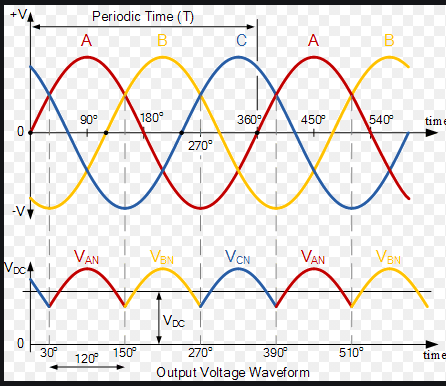
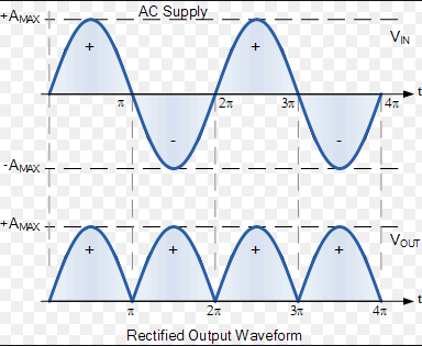
I just got a CHNC with GN6 controls. This has 90v HIAK servo drives. The previous owner "converted" this machine to single phase. I have been chasing quite a few issues down, one of them I think may be due to the extra ripple voltage I would be getting from having a rectified single phase vs 3 phase coming to the servo drives.
To size a suitable cap for this I would need to know what is a reasonable level of ripple voltage for input power to DC drives such as this.
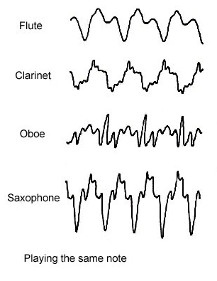
The problem I think may be a result of this is the velocity feedback I am getting from the revolvers looks like the sound wave of an instrument while the axis is in motion.... Also to be noted, is that this setup has the resolver and tach (I dont think I use) on the ballscrew and there is no feedback on the servo itself.
To size a suitable cap for this I would need to know what is a reasonable level of ripple voltage for input power to DC drives such as this.
The problem I think may be a result of this is the velocity feedback I am getting from the revolvers looks like the sound wave of an instrument while the axis is in motion.... Also to be noted, is that this setup has the resolver and tach (I dont think I use) on the ballscrew and there is no feedback on the servo itself.
Attachments:
Please Log in or Create an account to join the conversation.
- andypugh
-

- Offline
- Moderator
-

Less
More
- Posts: 19876
- Thank you received: 4642
06 Feb 2021 22:15 #197878
by andypugh
Replied by andypugh on topic Recommendation for Max ripple voltage for DC servo drives?
How are you reading the resolver velocity?
Please Log in or Create an account to join the conversation.
- Dbsharp
- Offline
- Junior Member
-
Less
More
- Posts: 29
- Thank you received: 2
07 Feb 2021 21:01 #197955
by Dbsharp
Replied by Dbsharp on topic Recommendation for Max ripple voltage for DC servo drives?
MESA 7I49, I have not had a chance yet to dig in and to verify this was actually setup correctly.
Please Log in or Create an account to join the conversation.
- andypugh
-
- Offline
- Moderator
-
Less
More
- Posts: 19876
- Thank you received: 4642
09 Feb 2021 00:29 #198106
by andypugh
Replied by andypugh on topic Recommendation for Max ripple voltage for DC servo drives?
Servos drives are generally pretty resilient to DC bus voltage variation. I doubt that is your problem.
The resolver excitation is via a low-voltage supply on the 7i49 so is isolated from the servo drive bus.
So I assume that you are trying to work out if the motor speed is changing with the bus voltage? I would guess not. What is the frequency of the variation? Does it seem plausible that the motor speed could change that fast?
Please Log in or Create an account to join the conversation.
- Dbsharp
- Offline
- Junior Member
-
Less
More
- Posts: 29
- Thank you received: 2
09 Feb 2021 00:56 - 09 Feb 2021 01:13 #198108
by Dbsharp
Replied by Dbsharp on topic Recommendation for Max ripple voltage for DC servo drives?
Thanks Andy. This video is of the x axis before I started messing with anything... The increments of motion seen here can be felt when the drives are off, I'm guessing the permanent magnets give it this feel. When I removed the X belt, it feels smooth as butter.
Not sure this is related at all to the waveform I have seen with the resolver feedback. I haven't measured the frequency of the feedback "ripple" from resolver velocity, but I think it would be within a rough order of magnitude of the ripple frequency from the rectified single phase.
Not sure this is related at all to the waveform I have seen with the resolver feedback. I haven't measured the frequency of the feedback "ripple" from resolver velocity, but I think it would be within a rough order of magnitude of the ripple frequency from the rectified single phase.
Last edit: 09 Feb 2021 01:13 by Dbsharp.
Please Log in or Create an account to join the conversation.
- Dbsharp
- Offline
- Junior Member
-
Less
More
- Posts: 29
- Thank you received: 2
09 Feb 2021 00:57 #198109
by Dbsharp
Replied by Dbsharp on topic Recommendation for Max ripple voltage for DC servo drives?
Just to illustrate the reason I suspect ripple voltage may be an issue, especially if the old cap is toast.
Please Log in or Create an account to join the conversation.
- scotth
- Away
- Elite Member
-

Less
More
- Posts: 242
- Thank you received: 61
09 Feb 2021 06:51 #198123
by scotth
Replied by scotth on topic Recommendation for Max ripple voltage for DC servo drives?
Have you looked at the sine and cosine feedback. I have seen missing one give the same results on other systems. This is just a guess never working with the 7i49 but inductosyn systems will do this and find null every half cycle.
Scott
Scott
Please Log in or Create an account to join the conversation.
- andypugh
-
- Offline
- Moderator
-
Less
More
- Posts: 19876
- Thank you received: 4642
09 Feb 2021 17:21 #198166
by andypugh
Replied by andypugh on topic Recommendation for Max ripple voltage for DC servo drives?
In the video are you driving the motor closed-loop at constant speed?
Please Log in or Create an account to join the conversation.
- andypugh
-
- Offline
- Moderator
-
Less
More
- Posts: 19876
- Thank you received: 4642
09 Feb 2021 17:21 #198167
by andypugh
Replied by andypugh on topic Recommendation for Max ripple voltage for DC servo drives?
Maybe make a degree disc (nound to be one on the net) and plot out the 7i49 angle against actual angle.
Please Log in or Create an account to join the conversation.
- Dbsharp
- Offline
- Junior Member
-
Less
More
- Posts: 29
- Thank you received: 2
10 Feb 2021 14:40 #198279
by Dbsharp
Replied by Dbsharp on topic Recommendation for Max ripple voltage for DC servo drives?
Thanks everybody for the suggestions. I will look into setting up the resolver properly and make sure it was done right. I assumed because it traveled the actual correct physical distance as linux cnc shows they would be setup correctly.
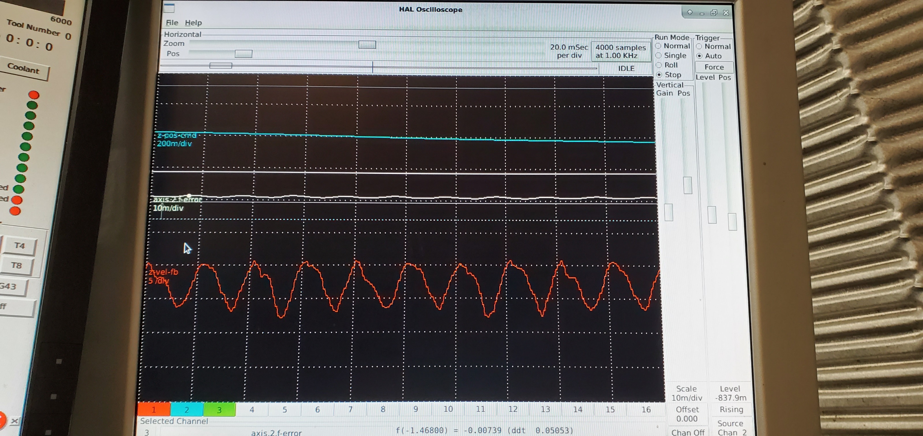
I did get a shot of this x axis last night at "15" ipm jog.... actually varied from 9 to 16 by halscope readings...
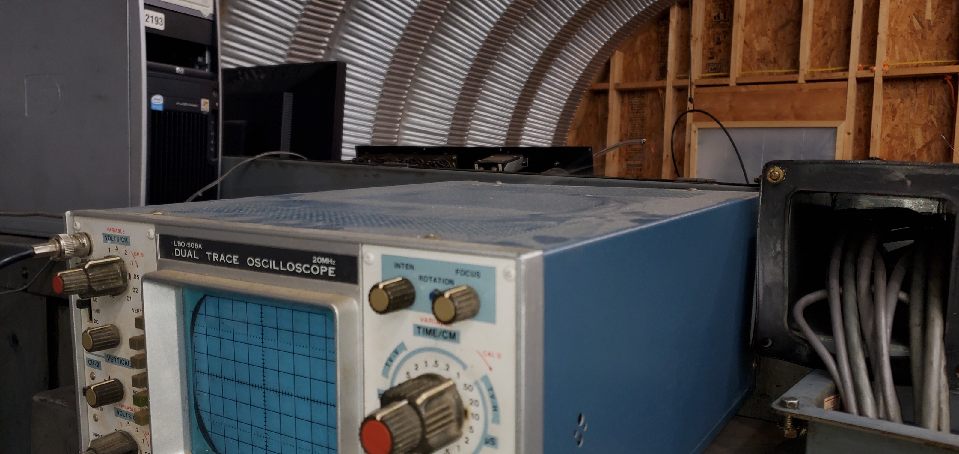
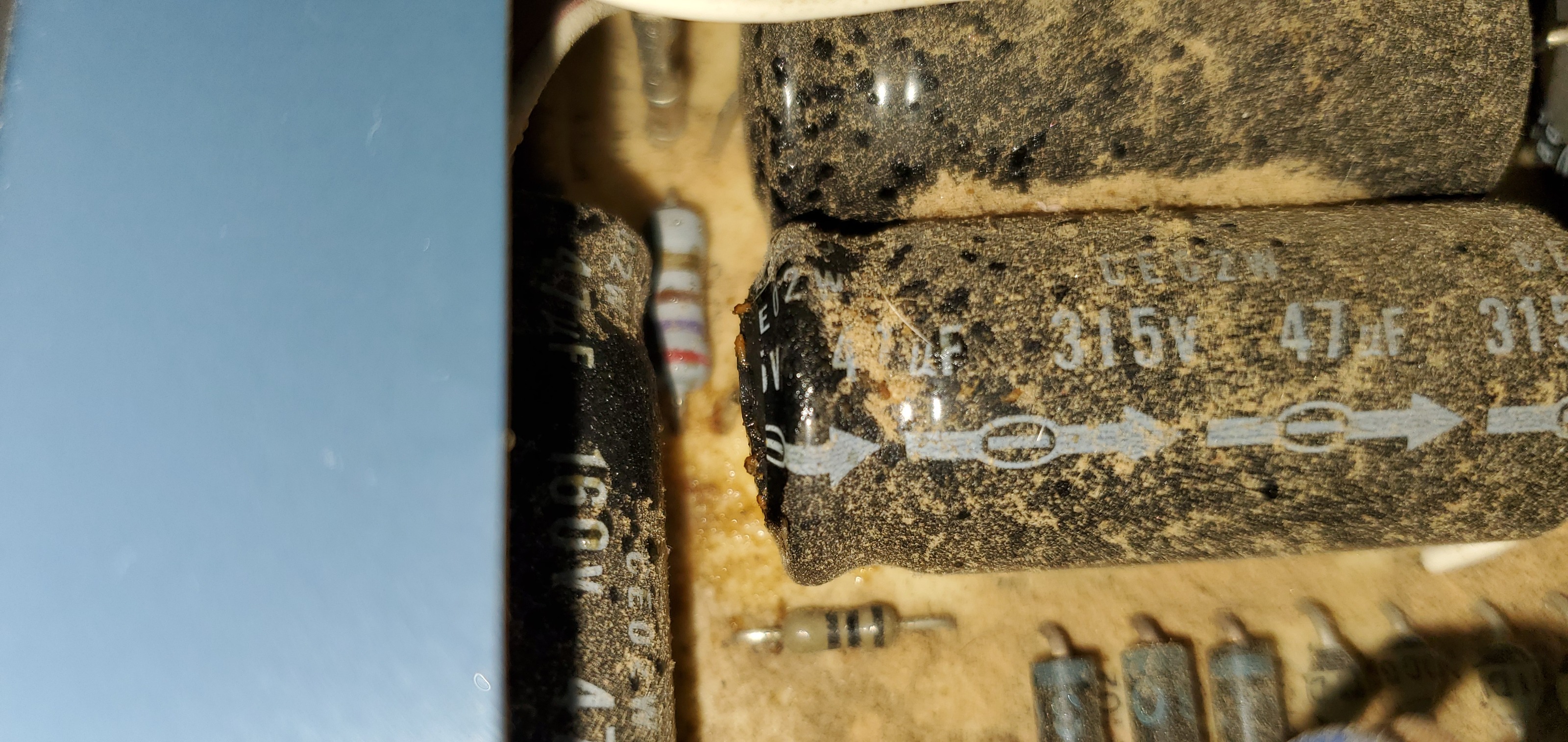
My silly scope let out the smoke last night when I was trying to view dc and servo output waveforms.... now I will attempt the open heart surgery on this old machine....
Also notable I measure 0 capacitance on the rectified dc input to the servos when off, I think they have a cap but its tucked behind other parts and I can just see the edges of a large cylinder. Maybe the enable input switches incoming power circuit when off?
Also notable I measured a little over 100v dc and I know this system is supposed to be 90v.
I did get a shot of this x axis last night at "15" ipm jog.... actually varied from 9 to 16 by halscope readings...
My silly scope let out the smoke last night when I was trying to view dc and servo output waveforms.... now I will attempt the open heart surgery on this old machine....
Also notable I measure 0 capacitance on the rectified dc input to the servos when off, I think they have a cap but its tucked behind other parts and I can just see the edges of a large cylinder. Maybe the enable input switches incoming power circuit when off?
Also notable I measured a little over 100v dc and I know this system is supposed to be 90v.
Attachments:
Please Log in or Create an account to join the conversation.
Time to create page: 0.238 seconds