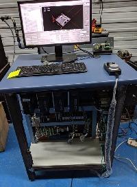
Brother TC-225 Retrofit and Robot integration
- PCW
-

- Offline
- Moderator
-

- Posts: 17478
- Thank you received: 5106
(or set the OUTPUT_SCALE to mm/s at 10V) and FF1=1.000
If you reduce the OUTPUT_SCALE to an appropriate number (say about 400)
you would need to reduce the PID terms correspondingly (to say P=220 =11000*400/20000)
etc
Please Log in or Create an account to join the conversation.
- bevins
-

- Offline
- Platinum Member
-

- Posts: 1942
- Thank you received: 338
Please Log in or Create an account to join the conversation.
- andypugh
-

- Offline
- Moderator
-

- Posts: 19752
- Thank you received: 4584
In one of the Halscope traces you have have an error of 0.015mm during a move. That's pretty good. But in others it is more like 0.5mm, which is terrible.
Please Log in or Create an account to join the conversation.
- timfaber
-
 Topic Author
- Offline
- Senior Member
-

- Posts: 64
- Thank you received: 3
No, you need _much_ more FF1
(or set the OUTPUT_SCALE to mm/s at 10V) and FF1=1.000
If you reduce the OUTPUT_SCALE to an appropriate number (say about 400)
you would need to reduce the PID terms correspondingly (to say P=220 =11000*400/20000)
etc
Ahh was wondering why my numbers where that high, thought ff1 was in mm/min.
What do you mean by 136 in the preview? The 0.015mm is my bad had the mouse hovering over a lower error value. Basically it is pretty bad. Will post some beter examples of f.error and feed later.Assuming a metric machine based on the 136 in the preview, and the suggestion that this isn't a room-sized machine..
In one of the Halscope traces you have have an error of 0.015mm during a move. That's pretty good. But in others it is more like 0.5mm, which is terrible.
Now in my understanding the way to reduce the f.error is by increasing P, or are there other parameters that infuence it?
Please Log in or Create an account to join the conversation.
- PCW
-

- Offline
- Moderator
-

- Posts: 17478
- Thank you received: 5106
if FF1 is wrong no amount of fussing with P,I,D will fix it
Please Log in or Create an account to join the conversation.
- timfaber
-
 Topic Author
- Offline
- Senior Member
-

- Posts: 64
- Thank you received: 3
Getting FF1 right is the first thing,
if FF1 is wrong no amount of fussing with P,I,D will fix it
Currently i'm working on tuning the axis, set the right ff1/output scale and am pretty happy with the behavior of the x axis, will post a plot later. now for the y-axis, came across what appear to be hunting but it's in the tuning of the drive. since it also did that with the original control. now there is no documentation to be found on the original drive, so maybe trail en error will be the only way? in the attachments is a plot the y-axis.
Please Log in or Create an account to join the conversation.
- timfaber
-
 Topic Author
- Offline
- Senior Member
-

- Posts: 64
- Thank you received: 3
[EDIT: Wrong attachment]
Please Log in or Create an account to join the conversation.
- timfaber
-
 Topic Author
- Offline
- Senior Member
-

- Posts: 64
- Thank you received: 3
Now i can't seem to control the rpm of the spindle, it always spins at max rpm. In the attachment pwmgen is 6000, encoder vel is -110 and spindle vel cmd is 60. now there seems to be some scaling error? Why does it translate vel-cmd of 60 to 6000 for pwmgen?
Furthermore, i would like to be able to orient the spindle. Now LaserK3000 has a rather complicated looking hal file for his tc215 to allow orient. I only want to be able the orient the spindle when doing a tool change.
BTW my spindle is a servo with a +-10v drive
also, is there a good way to test parts of my tool change script?
Please Log in or Create an account to join the conversation.
- PCW
-

- Offline
- Moderator
-

- Posts: 17478
- Thank you received: 5106
scale backwards. If you have any feedback (P or I or D terms not 0) you will have a runaway.
2. Encoder velocity is in RPS so -110 RPS is -6600 RPM (there is a encoder RPM velocity pin as well)
3. Can you post your current hal/ini files
Please Log in or Create an account to join the conversation.
- timfaber
-
 Topic Author
- Offline
- Senior Member
-

- Posts: 64
- Thank you received: 3
1. If you have forward spindle motion and the velocity is -110 you have the encoder
scale backwards. If you have any feedback (P or I or D terms not 0) you will have a runaway.
2. Encoder velocity is in RPS so -110 RPS is -6600 RPM (there is a encoder RPM velocity pin as well)
3. Can you post your current hal/ini files
Ahh cheers, the P=1 was the problem. Now the spindle works propperly, next up try to orient it.
Any advice on a good example setup or where to read up on orient?
Couldn't make much sense of the linuxcnc.org/docs/2.8/html/man/man9/orient.9.html
INI and HAL files in attachments
Please Log in or Create an account to join the conversation.
