- Hardware & Machines
- CNC Machines
- A retrofit of a Stanko SMO 32 CNC milling machine (Ukrainian clone of a Maho)
A retrofit of a Stanko SMO 32 CNC milling machine (Ukrainian clone of a Maho)
- drogus
- Offline
- Senior Member
-

Less
More
- Posts: 41
- Thank you received: 3
16 Jan 2022 12:18 - 24 Feb 2022 15:22 #232007
by drogus
A retrofit of a Stanko SMO 32 CNC milling machine (Ukrainian clone of a Maho) was created by drogus
Hi,
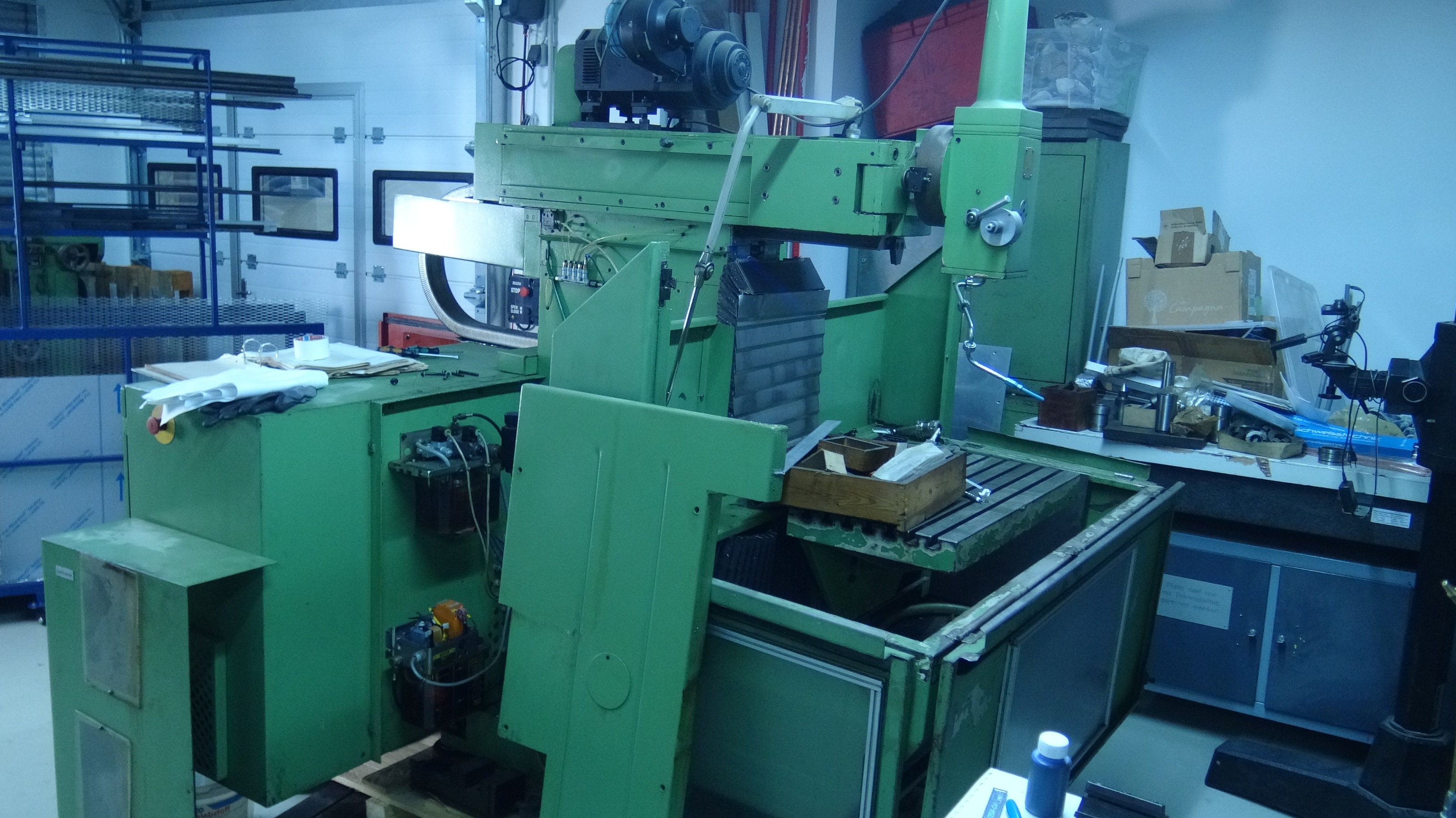
I'm planning to retrofit a Stanko SMO 32 CNC milling machine with LinuxCNC. It's a Ukrainian CNC milling machine that is quite similar to some of the Maho machines. The big upside is that almost all (or maybe all?) components are from the same companies that supplied Maho - Vögel lubrication system, Häve hydraulic pump, Indramat servo controllers, Heidenhain CNC control etc. Otherwise buying the machine wouldn't be the best option here in Germany. Or maybe anywhere as there are not many of them around as far as I know.
The machine has a work envelope of 500x420x400mm, so it's closest to the Maho 500 machines. It also uses the same spindle taper, ie. ISO40/SK40 and I think it's also the same type of hydraulic mounting for the tooling. One interesting thing that differs from the Mahos (or more specifically from E series) is that although the machine has a gearbox, there is also a variable speed control. The spindle speed is thus 20-4000RPM in 4 ranges. Retrofitting will then not be as easy as retrofitting Maho E2 series machine (ie. full VFD control), but also not as hard as retrofitting the E series with 18 gears (Hello RotarySMP )
)
Before retrofitting with LinuxCNC I plan to make it work as is as it looks like the machine is mostly functional. I think that the issues I’m facing at the moment wouldn’t be fixed by a retrofit, so it seems best to make it work first and only then look into swapping the CNC control. There are only 3 problematic pieces that I found so far:
1. The hydraulic pump used for tool clamping is not functioning properly
2. The lubrication pump doesn't turn on, which seems to be an electrical problem (most probably one of the relays is not turned on because of some kind of a problem}
3. The Z axis limit switch is malfunctioning - at some point I was able to power up the machine and move the axis, but sometimes there was an information about the limit being reached even though it was not in fact reached. I opened a thread about it a while ago: forum.linuxcnc.org/30-cnc-machines/41555...-with-limit-switches, I'll comment there when I have a solution, but it will need to wait for solving the pump problems
I wanted to open this thread to track progress, but if I need help on any specific thing I think I'll be opening separate threads and linking them here - that way it might be easier to find specific answers if someone comes from google or uses the search engine
For reference, here is the entire documentation with schematics: www.dropbox.com/sh/wlih7qlsraslpe1/AACT8...AKUHPnHZ8glHlTa?dl=0. I resized the files so they are not too big, but if someone needs a higher resolution for anything in there, let me know
Here are some photos of the electric cabinet: www.dropbox.com/sh/mp9mv18m1qa1olz/AAAmW...chp4JCs7S27ULGa?dl=0
I bought the machine without looking at it first, cause the price was good enough to risk it, but honestly I was quite lucky. I haven't worked on a CNC machine of this type before and I definitely haven't attempted any electrical fixes of this caliber, so when I was buying I haven't really known if all the schematics would be there. Fortunately it seems like there is a complete set of schematics, cause otherwise reverse engineering it would be nearly impossible for me.
Does anyone have this machine or used it in the past?
I'm planning to retrofit a Stanko SMO 32 CNC milling machine with LinuxCNC. It's a Ukrainian CNC milling machine that is quite similar to some of the Maho machines. The big upside is that almost all (or maybe all?) components are from the same companies that supplied Maho - Vögel lubrication system, Häve hydraulic pump, Indramat servo controllers, Heidenhain CNC control etc. Otherwise buying the machine wouldn't be the best option here in Germany. Or maybe anywhere as there are not many of them around as far as I know.
The machine has a work envelope of 500x420x400mm, so it's closest to the Maho 500 machines. It also uses the same spindle taper, ie. ISO40/SK40 and I think it's also the same type of hydraulic mounting for the tooling. One interesting thing that differs from the Mahos (or more specifically from E series) is that although the machine has a gearbox, there is also a variable speed control. The spindle speed is thus 20-4000RPM in 4 ranges. Retrofitting will then not be as easy as retrofitting Maho E2 series machine (ie. full VFD control), but also not as hard as retrofitting the E series with 18 gears (Hello RotarySMP
)Before retrofitting with LinuxCNC I plan to make it work as is as it looks like the machine is mostly functional. I think that the issues I’m facing at the moment wouldn’t be fixed by a retrofit, so it seems best to make it work first and only then look into swapping the CNC control. There are only 3 problematic pieces that I found so far:
1. The hydraulic pump used for tool clamping is not functioning properly
2. The lubrication pump doesn't turn on, which seems to be an electrical problem (most probably one of the relays is not turned on because of some kind of a problem}
3. The Z axis limit switch is malfunctioning - at some point I was able to power up the machine and move the axis, but sometimes there was an information about the limit being reached even though it was not in fact reached. I opened a thread about it a while ago: forum.linuxcnc.org/30-cnc-machines/41555...-with-limit-switches, I'll comment there when I have a solution, but it will need to wait for solving the pump problems
I wanted to open this thread to track progress, but if I need help on any specific thing I think I'll be opening separate threads and linking them here - that way it might be easier to find specific answers if someone comes from google or uses the search engine
For reference, here is the entire documentation with schematics: www.dropbox.com/sh/wlih7qlsraslpe1/AACT8...AKUHPnHZ8glHlTa?dl=0. I resized the files so they are not too big, but if someone needs a higher resolution for anything in there, let me know
Here are some photos of the electric cabinet: www.dropbox.com/sh/mp9mv18m1qa1olz/AAAmW...chp4JCs7S27ULGa?dl=0
I bought the machine without looking at it first, cause the price was good enough to risk it, but honestly I was quite lucky. I haven't worked on a CNC machine of this type before and I definitely haven't attempted any electrical fixes of this caliber, so when I was buying I haven't really known if all the schematics would be there. Fortunately it seems like there is a complete set of schematics, cause otherwise reverse engineering it would be nearly impossible for me.
Does anyone have this machine or used it in the past?
Attachments:
Last edit: 24 Feb 2022 15:22 by drogus.
Please Log in or Create an account to join the conversation.
- drogus
- Offline
- Senior Member
-
Less
More
- Posts: 41
- Thank you received: 3
16 Jan 2022 12:49 - 24 Feb 2022 15:29 #232010
by drogus
Replied by drogus on topic A retrofit of a Stanko SMO 32 CNC milling machine (Ukrainian clone of a Maho)
Ok, so the first problem "solved"
When powering the machine I got an error 47, which is described as "hydraulic unit not turned on". I wasn't sure if this is about a central lubrication system or a hydraulic pump for the tool holder and the brake, but my instinct was that it's the lubrication system (I'm sure that it's also possible to check it on the diagrams, but I haven't looked at them that much yet).
When looking at the connection diagram for the lubrication pump it can be noticed that voltage to the lubrication unit is supplied from the 157 node:

And then when looking at another diagram it can be seen that the power goes from the node 151 through a lot of relays to 157. I've measured the voltage on the 151 node and the voltage is supplied there, but there's no voltage on the node 157.
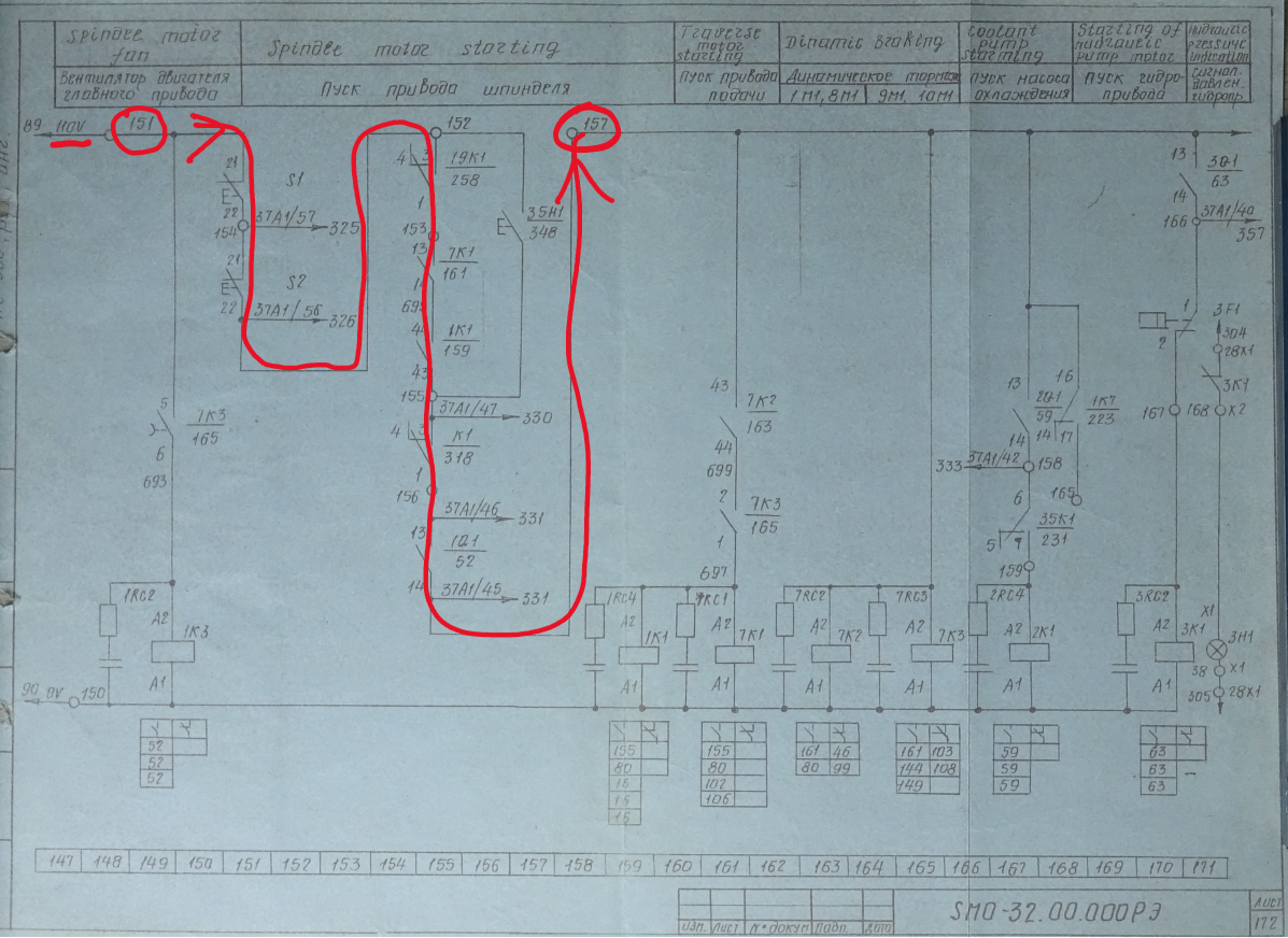
In order to check if the lubrication pump actually works I've jumper wired node 151 and 157 and indeed the lubrication pump starts and gets to a proper pressure. That's a huge relief, cause a new pump like that costs more than a 1000EUR and used units can go for a few hundred.
Now that the pump works I also get another error which can be translated into "CNC operation failed", which I'm pretty sure has something to do with one of the relays which isn't turned on. In the next days I'll be trying to debug which part between the node 151 and 157 fails to figure out what is still wrong there.
When powering the machine I got an error 47, which is described as "hydraulic unit not turned on". I wasn't sure if this is about a central lubrication system or a hydraulic pump for the tool holder and the brake, but my instinct was that it's the lubrication system (I'm sure that it's also possible to check it on the diagrams, but I haven't looked at them that much yet).
When looking at the connection diagram for the lubrication pump it can be noticed that voltage to the lubrication unit is supplied from the 157 node:
And then when looking at another diagram it can be seen that the power goes from the node 151 through a lot of relays to 157. I've measured the voltage on the 151 node and the voltage is supplied there, but there's no voltage on the node 157.
In order to check if the lubrication pump actually works I've jumper wired node 151 and 157 and indeed the lubrication pump starts and gets to a proper pressure. That's a huge relief, cause a new pump like that costs more than a 1000EUR and used units can go for a few hundred.
Now that the pump works I also get another error which can be translated into "CNC operation failed", which I'm pretty sure has something to do with one of the relays which isn't turned on. In the next days I'll be trying to debug which part between the node 151 and 157 fails to figure out what is still wrong there.
Attachments:
Last edit: 24 Feb 2022 15:29 by drogus.
Please Log in or Create an account to join the conversation.
- drogus
- Offline
- Senior Member
-
Less
More
- Posts: 41
- Thank you received: 3
17 Jan 2022 00:35 - 24 Feb 2022 15:29 #232086
by drogus
Replied by drogus on topic A retrofit of a Stanko SMO 32 CNC milling machine (Ukrainian clone of a Maho)
Today I had a long debugging session with the machine and I learned much more about the electrics, but also I had some weird issues going on. The problem that I'm currently looking into is the one I mentioned in my previous message: why there is no voltage at the 157 node. Let's take another look at the diagram:
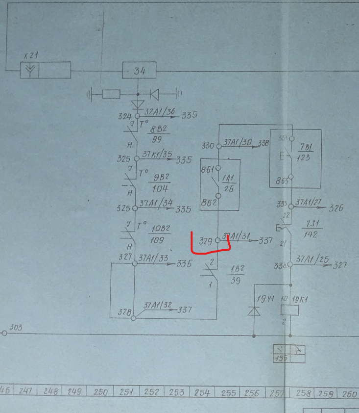
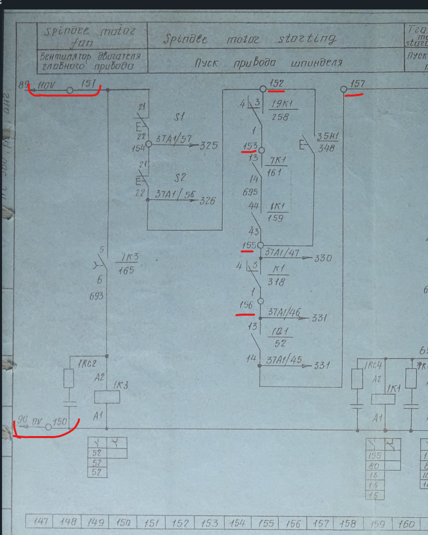 There we can see that the node 150 is 0V and 151 is 110V. Then we go through 152, 153, 155, 156 and 157 nodes. With that knowledge we can check voltage across points 150 and 151-157 and see at which point it stops. I measured 110V at 151 and 152, but no voltage on 153, so the problem is between nodes 152 and 153. The only think that is there is a contactor 19K1, which is further shown on the schematic part 258, so let's look there:
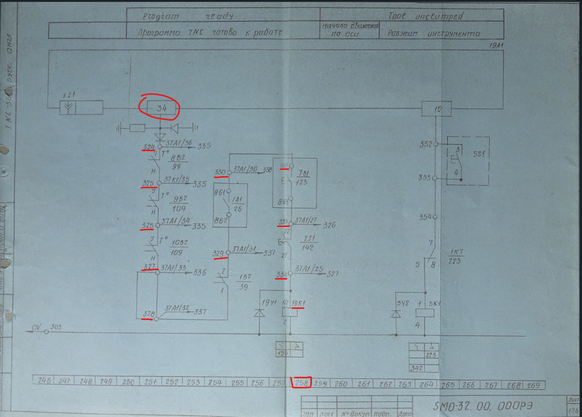 There should be a 24V coming to the node 324 and then it goes through a set of temperature sensors etc. Now, what I should have checked right away is if there is indeed 24V at the node 324, but I either forgot or checked incorrectly, cause I was thinking that the voltage is there. So I wanted to bypass all of the temperature sensors and I jump wired nodes 324 and 334 at which point the connector 19K1 was still not turned on (which, again, should have pointed me to the main problem - no 24V at 324). But at that time I was still under impression that something is wrong with the connector or sth like that. The connector in question is here:
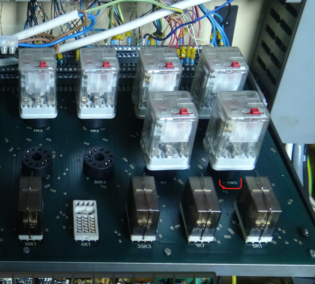 And it has a red button on top for a manual connection check. So I put sth on the connector to press the button and with all the other jumper wires I turned on the machine. I heard an unusual noise and when I checked the error number display I saw an error number 46, which I haven't seen before. It took me *a lot of time* to debug what just happened, but long story short is: the error was caused by one of the limit switches being pressed. So what happened was that some combination of me "bypassing" certain checks triggered servo motors to start spinning and the axis started moving. Which is kind of weird if you think about it, but it's hard to say what weird combination triggered it.
After noticing that indeed the axis are moved I got access to the servo motors and I moved the axis back to a neutral position, ie. so they don't trigger any of the limit switches. And then, after like 2 hours, I was at square one, ie. the mystery of the 19K1 connector was still unsolved and it was still my main issue at the moment. At the moment I don't have any other ideas, but I do know that there is 24V produced by a converter in the power supply section, so solving the puzzle might be as easy as finding a wire that's disconnected. Which is actually quite common in old machines - vibration during work may lead to screws in electrical terminals unscrewing themselves and then the machine may work for some time until it's moved in a way that the wire actually disconnects (which would make sense as I got the machine transported and then moved it around my workshop a few times).
After noticing that indeed the axis are moved I got access to the servo motors and I moved the axis back to a neutral position, ie. so they don't trigger any of the limit switches. And then, after like 2 hours, I was at square one, ie. the mystery of the 19K1 connector was still unsolved and it was still my main issue at the moment. At the moment I don't have any other ideas, but I do know that there is 24V produced by a converter in the power supply section, so solving the puzzle might be as easy as finding a wire that's disconnected. Which is actually quite common in old machines - vibration during work may lead to screws in electrical terminals unscrewing themselves and then the machine may work for some time until it's moved in a way that the wire actually disconnects (which would make sense as I got the machine transported and then moved it around my workshop a few times).
Attachments:
Last edit: 24 Feb 2022 15:29 by drogus.
Please Log in or Create an account to join the conversation.
- drogus
- Offline
- Senior Member
-
Less
More
- Posts: 41
- Thank you received: 3
18 Jan 2022 18:46 - 24 Feb 2022 15:29 #232313
by drogus
Replied by drogus on topic A retrofit of a Stanko SMO 32 CNC milling machine (Ukrainian clone of a Maho)
I had a bit of time today after work and I figured out two reasons of the current problems. As I mentioned in my last post, the main problem was that there was no 24V voltage on the node 324.
Now this is kind of weird. I know for a fact that the machine was able to boot much further than it does currently and so it should have gone through all those checks. Thus my thinking was that there was a connection from one of the 24V converters going to the node 324 and one of the connections got loose. But then I was trying to find all of the places where 324 wires were connected and I could find none that would be 24V. Which, again, was worrying a bit, but I figured out that I'm not going any further until I get those 24V and I connected line 700 (ie. positive side of one of the converters) to the 324 node. And indeed it helped and now I get 24V up to the point 329 here:
Which means that the next problem is in the main motor controller, Indramat TRK6 TSS 10. Which also seems to be indicated by the red LEDs:
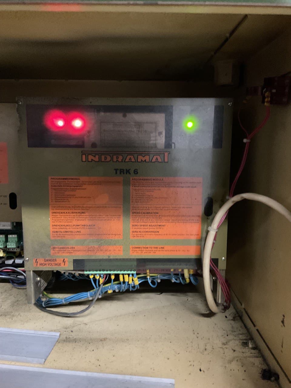
I'm not yet sure what could it be, unfortunately, and I'm hoping it's something simple, cause this device looks quite complex and a used one costs about a 1000EUR
Now this is kind of weird. I know for a fact that the machine was able to boot much further than it does currently and so it should have gone through all those checks. Thus my thinking was that there was a connection from one of the 24V converters going to the node 324 and one of the connections got loose. But then I was trying to find all of the places where 324 wires were connected and I could find none that would be 24V. Which, again, was worrying a bit, but I figured out that I'm not going any further until I get those 24V and I connected line 700 (ie. positive side of one of the converters) to the 324 node. And indeed it helped and now I get 24V up to the point 329 here:
Which means that the next problem is in the main motor controller, Indramat TRK6 TSS 10. Which also seems to be indicated by the red LEDs:
I'm not yet sure what could it be, unfortunately, and I'm hoping it's something simple, cause this device looks quite complex and a used one costs about a 1000EUR
Attachments:
Last edit: 24 Feb 2022 15:29 by drogus.
Please Log in or Create an account to join the conversation.
- drogus
- Offline
- Senior Member
-
Less
More
- Posts: 41
- Thank you received: 3
19 Jan 2022 09:01 - 24 Feb 2022 15:30 #232418
by drogus
Replied by drogus on topic A retrofit of a Stanko SMO 32 CNC milling machine (Ukrainian clone of a Maho)
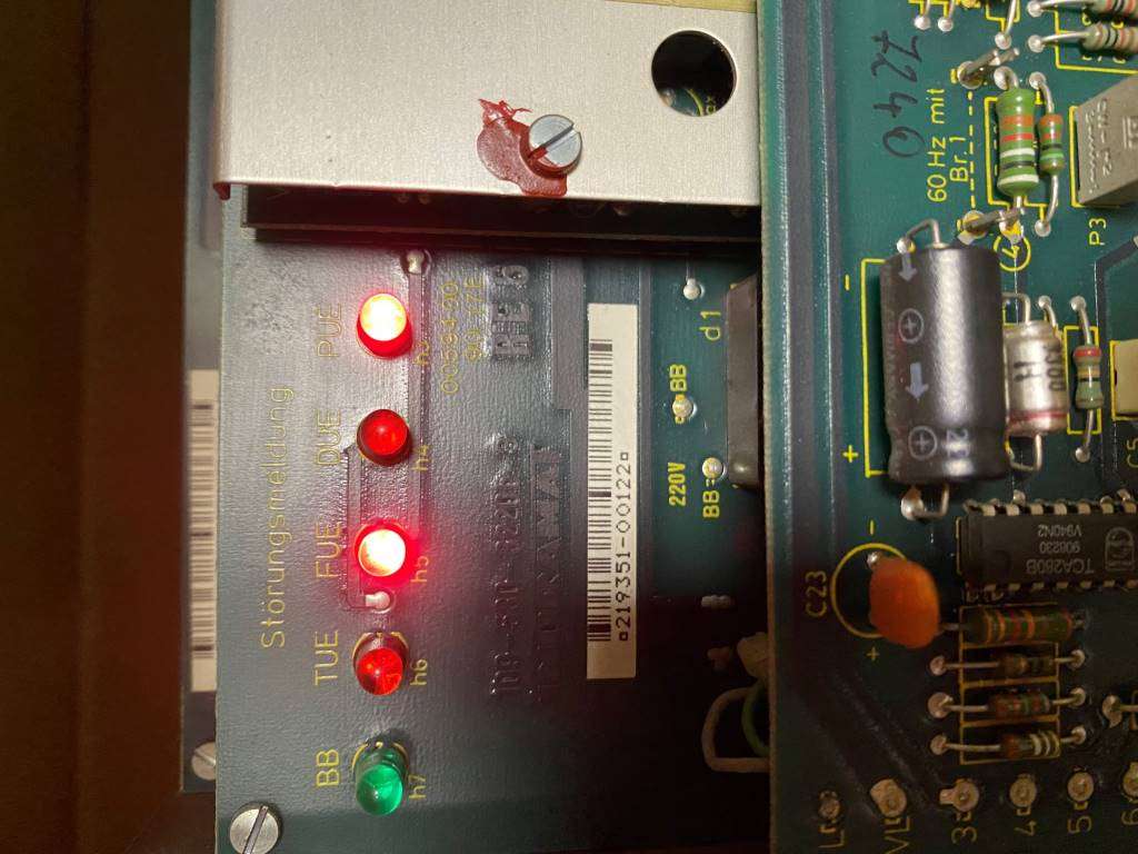
I won't get much time for debugging today, but I removed the front panel of the Indramat controller to see what errors are displayed and it's FUE and PUE.
Attachments:
Last edit: 24 Feb 2022 15:30 by drogus.
Please Log in or Create an account to join the conversation.
- Aciera
-

- Offline
- Administrator
-

Less
More
- Posts: 4725
- Thank you received: 2117
19 Jan 2022 18:51 #232468
by Aciera
Replied by Aciera on topic A retrofit of a Stanko SMO 32 CNC milling machine (Russian clone of a Maho)
Could it be that you are missing one of the three phases?
Maybe you've already found this:
de.industryarena.com/forum/mh-700-c--61820.html
Maybe you've already found this:
de.industryarena.com/forum/mh-700-c--61820.html
Please Log in or Create an account to join the conversation.
- drogus
- Offline
- Senior Member
-
Less
More
- Posts: 41
- Thank you received: 3
19 Jan 2022 21:10 - 24 Feb 2022 15:30 #232482
by drogus
Replied by drogus on topic A retrofit of a Stanko SMO 32 CNC milling machine (Ukrainian clone of a Maho)
I didn't have much time to debug today, but the problem is laying somewhere deeper. I've seen the discussion on the industryarena forum and thus the voltage on the input of the Indramat controller was the first thing I've checked. No voltage there, so I checked the fuses, but the fuses are fine. After a quick look at the schematics I've noticed that there is a 1K1 contactor just before the transformer:
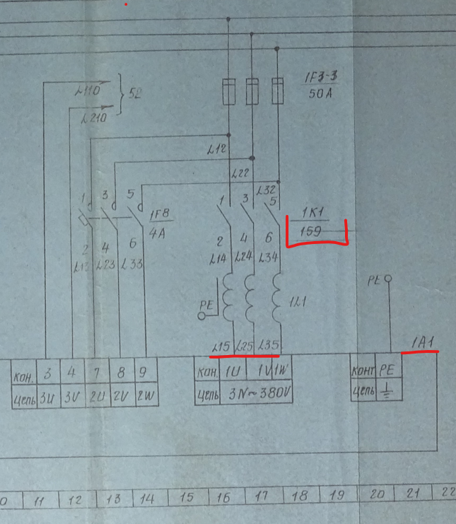
1A1 is a symbol for the Indramat motor controller, btw.
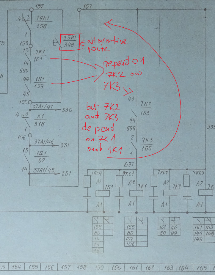
Now, here's the interesting part. So far I haven't fully understood how does the modules between nodes 151 and 157 work. And as 1K1 contactor is somewhere there I needed to look into it again (as you may recall I've been battling with this part before as this is essentially part that leads to the lubrication pump circuit). Now, the problem is that two sets of contactors depend on each other 7K1 and 1K1 contactors connect nodes between 153 and 155, but then in turn they are triggered by contactors 7K2 and 7K3, which are triggered by the node 157, which in turn, you guessed it, needs contactors 7K1 and 1K1 to pass the voltage. The solution to this is the 35H1 button - it will bypass the nodes between 152 and 155 and thus turn on the contactors there.
I'm a total noob when it comes to electrics, but to me it's kind of weird, is it something common in the CNC milling machine design? I'm guessing that the systems needed to turn on in a certain order, but I'm having a big "wtf" vibe here (but again, I don't know too much about electrics design).
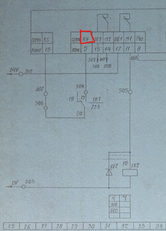
Anyways, knowing that I've checked the contactors and sure enough triggering those contactors results in the voltage being passed to the input of the Indramat controller. The problem with Indramat still persisted so I started checking other inputs and the problem seems to be that there is no 24V voltage on the RF input here:
I feel like I'm getting closer, cause there is not many parts left to debug. Unfortunately I'm leaving Berlin for a few days, so I won't be able to check it further, but I'm hoping that when I'm back I'll be able to finally track the problem, cause this feels like a one big wgack a mole game - as soon as I figure out the source of an error I need to go to what's causing the error and then what's causing the next error etc etc etc
1A1 is a symbol for the Indramat motor controller, btw.
Now, here's the interesting part. So far I haven't fully understood how does the modules between nodes 151 and 157 work. And as 1K1 contactor is somewhere there I needed to look into it again (as you may recall I've been battling with this part before as this is essentially part that leads to the lubrication pump circuit). Now, the problem is that two sets of contactors depend on each other 7K1 and 1K1 contactors connect nodes between 153 and 155, but then in turn they are triggered by contactors 7K2 and 7K3, which are triggered by the node 157, which in turn, you guessed it, needs contactors 7K1 and 1K1 to pass the voltage. The solution to this is the 35H1 button - it will bypass the nodes between 152 and 155 and thus turn on the contactors there.
I'm a total noob when it comes to electrics, but to me it's kind of weird, is it something common in the CNC milling machine design? I'm guessing that the systems needed to turn on in a certain order, but I'm having a big "wtf" vibe here (but again, I don't know too much about electrics design).
Anyways, knowing that I've checked the contactors and sure enough triggering those contactors results in the voltage being passed to the input of the Indramat controller. The problem with Indramat still persisted so I started checking other inputs and the problem seems to be that there is no 24V voltage on the RF input here:
I feel like I'm getting closer, cause there is not many parts left to debug. Unfortunately I'm leaving Berlin for a few days, so I won't be able to check it further, but I'm hoping that when I'm back I'll be able to finally track the problem, cause this feels like a one big wgack a mole game - as soon as I figure out the source of an error I need to go to what's causing the error and then what's causing the next error etc etc etc
Attachments:
Last edit: 24 Feb 2022 15:30 by drogus.
Please Log in or Create an account to join the conversation.
- Aciera
-
- Offline
- Administrator
-
Less
More
- Posts: 4725
- Thank you received: 2117
20 Jan 2022 08:55 - 20 Jan 2022 09:08 #232503
by Aciera
Replied by Aciera on topic A retrofit of a Stanko SMO 32 CNC milling machine (Russian clone of a Maho)
7K1, 1K1 and 19K1 together with 35H1 form a latching mechanism (Selbsthalteschaltung) that is widely used even today. If no fault is present, pressing the button 35H1 will bypass the open contacts and activate the coils of the contactors thus closing the latch and the button can be released. Any kind of machine stop command will open one or more of the contacts 7K1, 1K1, 19K1 and the machine will shut down. The machine will not restart without the operator pushing the button 35H1 again, which I presume is something like 'Machine Start'. Just think about what happen after a power failure, if you just had a manual switch to turn on the machine it would just restart after power comes back on. With a latch like this the operator will have to manually push the button 35H1 before anything turns on.
On top of that there will be a sequence involved where certain thing needs to be running before others can be turned on.
The combinations of contacts, buttons and coils can be quite complex but still easier to troubleshoot than dealing with an undocumented PLC or safety relay.
Note that using two contactors for what could have been done with just one is usually a safety feature in case one of them 'sticks' and doesn't break the contact the other will still open and stop the machine. This is still done in modern applications.
Last edit: 20 Jan 2022 09:08 by Aciera.
The following user(s) said Thank You: tommylight, Clive S, drogus
Please Log in or Create an account to join the conversation.
- drogus
- Offline
- Senior Member
-
Less
More
- Posts: 41
- Thank you received: 3
20 Jan 2022 12:20 - 24 Feb 2022 15:30 #232518
by drogus
Replied by drogus on topic A retrofit of a Stanko SMO 32 CNC milling machine (Ukrainian clone of a Maho)
Thanks for the explanation Aciera, it makes perfect sense now!
Last edit: 24 Feb 2022 15:30 by drogus.
Please Log in or Create an account to join the conversation.
- drogus
- Offline
- Senior Member
-
Less
More
- Posts: 41
- Thank you received: 3
24 Jan 2022 10:50 #232943
by drogus
Replied by drogus on topic A retrofit of a Stanko SMO 32 CNC milling machine (Russian clone of a Maho)
I got back to Berlin and I had a few minutes to check the machine before work and I think that the main problem is that the logic unit, ie Heidenhain LE 360C doesn't output 24V on any of the points where this voltage is needed to start the machine. In
one of my previous messages
I mentioned that there's no 24V in the point 324 and I wrongly assumed it had to be connected to 24V rails somewhere. It seems like this point, just like 316 (schema 223) and 352 (schema 264) need a signal from the logic unit.
Now, I have exactly zero idea why this is the case, but at this point I think I might start ordering parts for a retrofit, cause I have a feeling that connecting LinuxCNC to the machine might be easier than to debug the logic unit. I'm going to try to find a manual for the logic unit and see if I can learn anything that way.
Anyone has any experience with debugging stuff like that? I have an old oscilloscope, so I could measure some signals if that's needed, but it has only 2 channels.
Please Log in or Create an account to join the conversation.
- Hardware & Machines
- CNC Machines
- A retrofit of a Stanko SMO 32 CNC milling machine (Ukrainian clone of a Maho)
Time to create page: 0.487 seconds