- Hardware & Machines
- CNC Machines
- A retrofit of a Stanko SMO 32 CNC milling machine (Ukrainian clone of a Maho)
A retrofit of a Stanko SMO 32 CNC milling machine (Ukrainian clone of a Maho)
- Aciera
-

- Offline
- Administrator
-

- Posts: 4707
- Thank you received: 2106
I presume symbol 19A1 is the electronic controller you refer to as the 'logic unit'. If the 24V supply is not there then of course the controller can't be running. If the 24V supply is there then I would expect some kind of indicator on the device showing it's state. (ie RUN or Fault or something). If it seems to be running then it's likely not getting an input signal needed to satisfy the internal logic. In this case you will want to get a clear picture of what the logic inputs are connected to on the machine (ie sensors, buttons, switches etc) and try to deduce from that what might be required for the machine to be running. As a rule of thumb I would check the inputs and see which have a 24V signal coming in and which don't, likely it's an input that is missing a 24V signal that is blocking the logic but not necessarily.
There may of course be a remote chance to read the logic program from the device through a serial interface but you'd have to really be in love with the old controller to put in that much effort to save it.
Please Log in or Create an account to join the conversation.
- drogus
- Offline
- Senior Member
-

- Posts: 41
- Thank you received: 3
So I think what you suggest is correct, ie. this must have to do something with the inputs. The problem is that this part of the wiring differs from the schematics. For example at the column 278 here there are some switches that are described as "microswitches of the enclosure, lock":
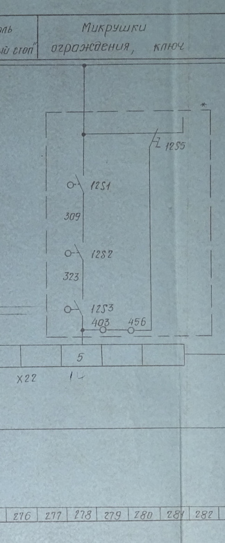
so my first thought was: OK, maybe it's something as dumb as some kind of switch that checks if the enclosure is opened, but then I couldn't find any switch like that and it turned out that the points listed there (403, 456) are not connected to the input. Which looks like maybe on some machines there were switches like that, but not on that particular machines. I will still maybe go over some of the points that are in fact connected to the inputs over the weekend, but I agree with you - if it's not something I can catch quickly, it won't be worth it to debug the thing. Especially that I can probably sell the controller and the display/keyboard assembly for a decent price. One drawback of getting rid of the entire controller will be that I will have to give up the EXE components as they are integrated inside the controller, but there's lots of standalone EXE modules on Ebay and most of them are in 60-80EUR range, so that's not a big problem. And then the placement of the controller would work great for a motherboard with LinuxCNC, so again, I would prefer to get rid of it.
Anyways, I'll write an update soon, but I'm close to pull the trigger on the Mesa cards

Attachments:
Please Log in or Create an account to join the conversation.
- Aciera
-
- Offline
- Administrator
-
- Posts: 4707
- Thank you received: 2106
I would think that is why that part of the schematics is in a dashed box marked with an asterisk (*) in the top right corner. (ie. this part is optional)The problem is that this part of the wiring differs from the schematics. For example at the column 278 here there are some switches that are described as "microswitches of the enclosure, lock":
Please Log in or Create an account to join the conversation.
- drogus
- Offline
- Senior Member
-
- Posts: 41
- Thank you received: 3
Please Log in or Create an account to join the conversation.
- drogus
- Offline
- Senior Member
-
- Posts: 41
- Thank you received: 3
Points 160 and 303 are basically connected to ground.
376 is quite interesting - it's coupled with node 307, which is one of the outputs which is one of the outputs. In the column 271 it's described as a "reaction for the function M, T". In the column 234 (for the outputs) it's described as "address M". Not sure what that could mean, sth about a motor? I'll need to check the voltage on the node 307 and if the contactor connected there works correctly.
400-402 points are for the motor control, likely not important for starting up.
405-421 look like they're used when changing gears, so again, most likely not important for startup
Please Log in or Create an account to join the conversation.
- Aciera
-
- Offline
- Administrator
-
- Posts: 4707
- Thank you received: 2106
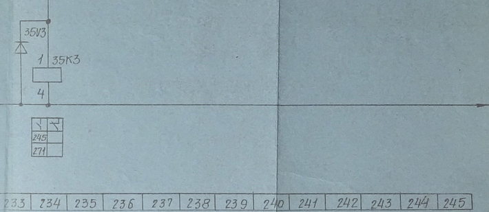
Just had a look, according to the schematic there is another contact of 35K3 but it clearly not at column 245 as indicated:
Are you still only getting fault "47" on the indicator in the electric cabinet (Störstellenmelder) ?
Also, as you probably know, there seems to be a fairly extensive explanation of the electrics starting on page 78.
Attachments:
Please Log in or Create an account to join the conversation.
- drogus
- Offline
- Senior Member
-
- Posts: 41
- Thank you received: 3
Thanks a lot and no, I didn't know about this part of the manual! My German is quite basic, so I was translating only selected parts of the manual and I haven't realized there is anything like that. Skimming through those pages now seems like they might have been very helpful in the past weeks lol. I'll do a translation so I can understand it better> Are you still only getting fault "47" on the indicator in the electric cabinet (Störstellenmelder) ?
Yes, but I think it would go away as soon as I'm able to fix whatever the problem with the controller is
Please Log in or Create an account to join the conversation.
- drogus
- Offline
- Senior Member
-
- Posts: 41
- Thank you received: 3
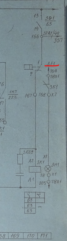
So I checked the nodes 166 and 167 and sure enough there was 110V between 166 and the ground and no voltage on 167.
Now I started looking for the 3F1 device and it's on the hydraulic pump:
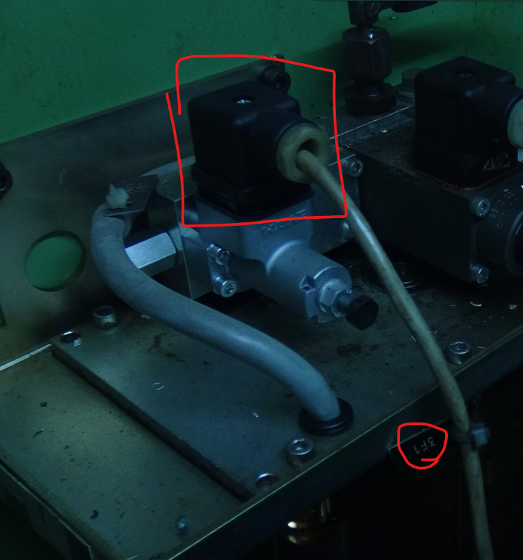
Before I thought that it's a pressure check, but now I'm not sure. Anyone with the similar pump knows how this thing works?
Now that I'm thinking about it maybe it's a minimum oil level check. There are no markings on the minimum level and the pressure gauge is on the right I think. So maybe I just need to add oil?
Attachments:
Please Log in or Create an account to join the conversation.
- drogus
- Offline
- Senior Member
-
- Posts: 41
- Thank you received: 3
update:
There is something definitely going on in there. I unscrewed the top of the device to uncover contacts and there is a connection between the contacts when the machine is off. But then as soon as the voltage comes in the connection is closed. I thought that maybe the pump is getting up to the pressure too fast to notice, but that would be weird. Just in case I asked another person to hold the "hydraulics on" button while I was looking at the pump and it didn't move at all, so yeah, it seems that something is off about the pressure switch. I will buy the oil to top it up just in case, but if that won't help I'll maybe buy a replacement switch.
Please Log in or Create an account to join the conversation.
- Aciera
-
- Offline
- Administrator
-
- Posts: 4707
- Thank you received: 2106
Page 105:
" The motor of the hydraulic system 3M1 is turned on if the pressure switch 3F1 switches on. Meaning, if the contact 3F1 (166-167) is closed and the starter 3K1 is turned on."
The fact that the contact is open could be to a malfunction of the mechanics of the switch or a bad electrical connection to the cabinet.
I would take off the connector cap and check the contact right at the switch with an ohm meter.
[edit]
Topping up the oil will not likely affect the problem since the contact is supposed to be closed when the oil pressure is low and I presume the hydraulic system is not under pressure at the moment.
[edit2]
Seems I was a bit too late with all that.
Please Log in or Create an account to join the conversation.
- Hardware & Machines
- CNC Machines
- A retrofit of a Stanko SMO 32 CNC milling machine (Ukrainian clone of a Maho)