Wiring of oil pump.

More
4 years 3 months ago #247469 by deus
Replied by deus on topic Wiring of oil pump.
It is Australia with 240V /50Hz single phase with one hot conductor.

Please Log in or Create an account to join the conversation.

More
4 years 3 months ago #247470 by spumco
Replied by spumco on topic Wiring of oil pump.
Gotcha.

Do you want the ability to manually operate the pump using the on-board "FEED" button, or exclusively through LCNC?

Please Log in or Create an account to join the conversation.

More
4 years 3 months ago #247473 by spumco
Replied by spumco on topic Wiring of oil pump.
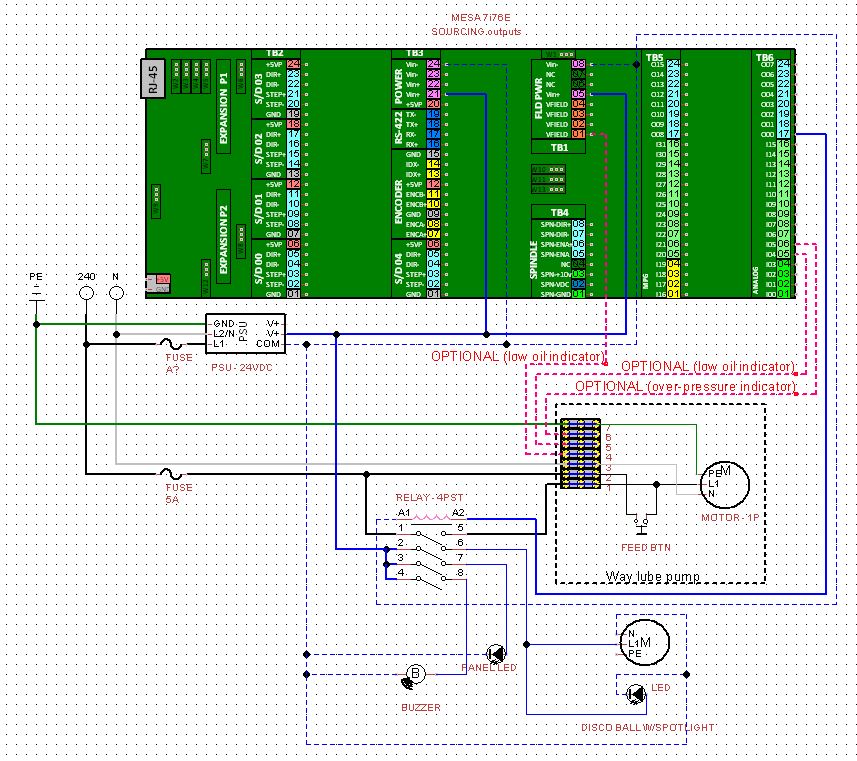
I'm shamelessly procrastinating on my own LCNC project, so here's a diagram of what I think you're after

NOTE - you did write that you're using a 7i76E, not "ED".  Those are sourcing outputs and I've drawn it as such.  If you're using an "ED" the 24vdc connections will be different.
  • The pump is a 240VAC single-phase.  It can be powered by
    • single 240v conductor + neutral (your arrangement), or
    • by 120v + 120v conductors and no neutral (US wiring)
  • Break the 'hot' line with the SSR ("R") and treat "T" as the neutral.
    • Note - not a fan of SSR's in certain applications as they tend to fail closed (on)
    • Should be fine here however as long as you've got a real estop contactor or main disconnect on the machine.
    • My preference would be to use a DPST or DPDT mechanical relay, and use the second set of contacts to trigger a pilot light.  Would make a nice control panel trinket, and is a good indicator of when the pump is powered with zero LCNC programming required.
      • Contact #1 - 240 pump power
      • Contact #2 - 24vdc to a yellow "LUBE ON" lamp
  • Hot line goes to terminals #1 & #2.
    • #1 is switched with the SSR by LCNC using the 7i76E output
    • #2 is always-hot, permitting local pump control using the "FEED" button on the pump assy.
  • Neutral is internally fused
  • Optional
    • There's a float switch indicator circuit internal to the way lube assy.  Feel free to connect that to an input on the 7i76E so you can trigger an on-screen message to refill the pump.
    • These look like dry contacts, so should be fine with the 24VDC to/from 7i76E.  But leave disconnected until you power the pump and verify there's no voltage at those terminals.
  • Extra-optional, not drawn
    • Connect terminal #6 to another 7i76E input and you can have a pump over-pressure alarm
Double-check everything.  As usual, if you burn down your universe it's not my fault.

PS - there are some examples of lube pump control using Classic Ladder in the CL sub-forum.  Generally controls based on a timer that counts while some 'axis-is-moving' signal is on, plus a manual override to prime it.


Please Log in or Create an account to join the conversation.

More
4 years 3 months ago #247479 by spumco
Replied by spumco on topic Wiring of oil pump.
REV2 - Significant improvements:

1. Optional pressure indicator circuit to LCNC
2. Panel indicator w/ST4P relay
3. Siren, for pump activation notification while you're outside the shop
4. Motorized disco ball, w/ spotlight, because safety regulations require it.

 
The following user(s) said Thank You: arvidb, tommylight, pommen, deus

Please Log in or Create an account to join the conversation.

More
4 years 3 months ago #247552 by deus
Replied by deus on topic Wiring of oil pump.
That is great spumco. Thank you so so much. What software did you use? I will still to document all my wiring...
I am just in the process of wiring it all up - pretty much per your drawing with a few changes:
  • As you said the neutral is internally fused. I will rewire it and move it to the hot side. I have also a circuit breaker of 6A which should give enough protection.
  • I took your advice on board and connected the pump with my main switch as well as my e-stop circuit (it can't hurt). 
  • I currently have only a relay that has one switch, hence, I was thinking of putting the indicator LED light in parallel to the relay.
  • I only have a four core cable - do you think it is ok (good enough practice) to use the 24V from the MESA that switches the relay to run through the oil pump sensors too (I will read the sensors only when the device is on anyway)? Or better to take the power supply from the MESA field power?

I will put the disco ball and the sound system on a separate circuit when I have the completion party of this cnc. You are invited... if you can make it to OZ. image missing /media/kunena/emoticons/cool.png

Thanks a million!!!


Please Log in or Create an account to join the conversation.

More
4 years 3 months ago #247571 by spumco
Replied by spumco on topic Wiring of oil pump.
Hope you find it useful.
Code:
I currently have only a relay that has one switch, hence, I was thinking of putting the indicator LED light in parallel to the relay.

Need to be careful here.  The 7i76E has a limit of 350ma per output; get the max current draw for both the relay and the LED and if the combined current draw is lower you're fine.  If not, you can use a second output to drive the LED.

Better option is to buy another relay - either a second single-pole or substitute a double-pole for the single-pole SSR.

Relays are cheap.  Just avoid the 'relay modules' which come on a card with 1/2/.../16 little relays soldered on to a board unless you're really pressed for space.  If one of the relays dies it's a pain to replace it (soldering).

ebay is a great source for DIN-rail relay mounts & miniature card-type relays.  Here's an example of a non-soldered relay module:

el-cheapo relay module

Should work well for controlling various CNC trinkets.  The relays are easily replaceable, inexpensive, and built-in snubber diodes.

Example of what to avoid:

soldered relay module

Ok for really tight mounting, otherwise avoid.

For the ultimate in grown-up industrial relays, you might find stuff like this:

Grown-up relays

Assuming those aren't fakes, that's the sort of stuff used in grown-up equipment.  The "card" relays plug in to the mounts and you can buy a variety of different relay coil voltages and features (gold contacts).  They can be connected/linked together so a single ground wire is needed for multiple relays (coil side), and a single power wire is needed on the contact side.  And you can get them in single, double, triple, and quad contacts - housings are different widths - that all gang together.

Some even have timers that can be plugged in to the relay which turn a standard relay/mount in to a nice multi-function timer relay.

Phoenix is not the only brand, BTW.
Code:
What software did you use?

I use TinyCAD; I've already drawn quite a few custom components (Mesa boards & servo drives), so I stick with it despite some other software probably being better.  There's a good discussion on electrical drawing software here:

software
Code:
I only have a four core cable - do you think it is ok (good enough practice) to use the 24V from the MESA that switches the relay to run through the oil pump sensors too (I will read the sensors only when the device is on anyway)? Or better to take the power supply from the MESA field power?
  • You can strip the cable open and use the individual conductors if needed.
  • The control relay should be inside your electrical enclosure with individual/discrete wires from the Mesa to the relay(s).
    • (inside enclosure)
      • Individual wires/conductors from Mesa output to relay coil
      • Individual wires from 240v to relay contacts
    • (outside enclosure - known as "field wiring")
      • One 'cable' for 240v from relay contacts to pump (3 conductors plus ground wire)
      • One 'cable' for 24vdc from Mesa field voltage to the sensors and back to Mesa input(s) (2 or 3 conductors)
    • Don't misunderstand drawing as a physical layout - it's an electrical layout.
  • No, it's not good practice to use the Mesa relay control output to power the pump's internal sensor switches.
    • If wired this way the sensors will only be active when the pump is running - a comparatively short period of time.
    • Plus you'll have to add the Mesa's input current draw to the total current seen by the Mesa output.
    • Keep them separate.  If you follow my suggestion above about physical cabling, you'll have no issue powering the sensor switches via the field power.
  • If you're pressed for cables, a good source is bulk or old ethernet cables.  You can chop them up and you've got 8 conductors inside.
    • These are only good for low-voltage, low current signaling circuits or really low-current relay coils
    • Try to find 24AWG cables.  26 or 28 are miserable to make connections if you've got fat fingers.
    • Try to find stranded conductors - solid are ok but they'll eventually break if on a moving/vibrating component
    • The ultimate in cheapo good stuff is 24AWG, stranded, individually and overall shielded ethernet cables. They've got twisted pairs, too.  I use these for signals that are critical and subject to electrical noise (step/direction on drives, analog 0-10v signals to VFDs, etc.)
Good luck.  I've really got to stop procratinating on my own stuff now...image missing /media/kunena/emoticons/sad.png
The following user(s) said Thank You: arvidb, deus

Please Log in or Create an account to join the conversation.

Time to create page: 0.286 seconds
Powered by Kunena Forum