dxf2gcode - plasma enhancements
- Joco
-
 Topic Author
- Offline
- Platinum Member
-

Less
More
- Posts: 532
- Thank you received: 327
13 May 2021 10:15 #208722
by Joco
Replied by Joco on topic dxf2gcode - plasma enhancements
Yeah - I'm discovering that challenge re small parts. Interested in the "useless" comment as most else of what I have seen indicates its a good feature to have. But I do acknowledge just cose you have a hammer in the toolbox doesn't mean everything needs the hammer.
Anyway, pretty much have all the leads stuff done now. Just some final refinements and will be done. At least for the use case I am looking to have solved for.
Cheers - J.
Anyway, pretty much have all the leads stuff done now. Just some final refinements and will be done. At least for the use case I am looking to have solved for.
Cheers - J.
Please Log in or Create an account to join the conversation.
- rodw
-

- Offline
- Platinum Member
-
Less
More
- Posts: 11968
- Thank you received: 4079
14 May 2021 11:26 #208792
by rodw
Replied by rodw on topic dxf2gcode - plasma enhancements
Perpendicular leadin and no leadout is whats generally recommended, even from Jim Colt from Hypertherm (retired)
Its what I use after a few trials ages ago.
Its what I use after a few trials ages ago.
The following user(s) said Thank You: Joco
Please Log in or Create an account to join the conversation.
- Joco
-
Topic Author
- Offline
- Platinum Member
-
Less
More
- Posts: 532
- Thank you received: 327
14 May 2021 19:33 #208846
by Joco
Replied by Joco on topic dxf2gcode - plasma enhancements
That’s awesome info Rod. Thanks for that advice on a proven formula. I’ll make that the default.
Any gems on length of the leadin?
Cheers- J.
Any gems on length of the leadin?
Cheers- J.
The following user(s) said Thank You: rodw
Please Log in or Create an account to join the conversation.
- rodw
-
- Offline
- Platinum Member
-
Less
More
- Posts: 11968
- Thank you received: 4079
14 May 2021 21:01 #208852
by rodw
Replied by rodw on topic dxf2gcode - plasma enhancements
I usually work on about 3mm but thicker material but on a 16mm job I set up yesterday, I used 5mm. 120 amps blows a bit of a crater on piercing! For automation, maybe 3x the kerf width might work. That would put my 16mm job at 8mm leadin which is probably better. I might change it now you made me think about it. Its a long time since I cut it.
Please Log in or Create an account to join the conversation.
- tommylight
-

- Offline
- Moderator
-

Less
More
- Posts: 21670
- Thank you received: 7401
14 May 2021 22:12 #208863
by tommylight
But i rarely cut anything thick, avoiding it for now!")
Replied by tommylight on topic dxf2gcode - plasma enhancements
+1I usually work on about 3mm ....
But i rarely cut anything thick, avoiding it for now!
Please Log in or Create an account to join the conversation.
- rodw
-
- Offline
- Platinum Member
-
Less
More
- Posts: 11968
- Thank you received: 4079
14 May 2021 22:30 #208866
by rodw
Replied by rodw on topic dxf2gcode - plasma enhancements
+1But i rarely cut anything thick, avoiding it for now!
Please Log in or Create an account to join the conversation.
- snowgoer540
-

- Offline
- Moderator
-
Less
More
- Posts: 2552
- Thank you received: 884
15 May 2021 01:08 #208882
by snowgoer540
Replied by snowgoer540 on topic dxf2gcode - plasma enhancements
I think that’s a good default.
But also, it’s good to have options. If there’s one thing I’ve learned in the plasma journey it’s that there is no “one size fits all”.
What works for one doesn’t seem to work for another, etc etc. so long as there’s the ability to add lead ins and lead outs, arcs, perp, etc. I think that’s a good thing.
Please Log in or Create an account to join the conversation.
- Joco
-
Topic Author
- Offline
- Platinum Member
-
Less
More
- Posts: 532
- Thank you received: 327
15 May 2021 10:24 - 15 May 2021 21:44 #208900
by Joco
Replied by Joco on topic dxf2gcode - plasma enhancements
Current situation in my plasma-leads branch is:
[1] CAM baked compensated path for kerf width (tool diameter) WITH lead-in/out
[2] Leads have size driven by tool radius + start radius
[3] Two styles of Leads. Line and Arc
[4] Default lead style is Line
[5] DXF layer named "PLASMA" drives special behaviour
[6] Auto cutter compensation setting is aware of PLASMA layer naming and auto adjusts cut/offset direction based on detection of external contours and internal contours. External are CW cut with compensation to outside, Internal are CCW cut with compensation to inside. This based on my understanding that plasma swirls CW and from reading you want to be doing what is in effect climb milling against the target edge. If that swirl direction is different Northern Hemisphere v's Southern (like water going down a plughole is) then please let me know!
[7] Switches that can be part of the layer name include the following. These apply to all geometry on a layer
- Slo:1 <-- supresses lead-outs
- Sli:1 <-- supress lead-ins
- Lit:0 <-- sets lead in type arc
- Lit:1 <-- sets lead in type line
- Lot:0 <-- sets lead out type arc
- Lot:1 <-- sets lead out type line
example layer name that would suppress leadouts. Note that the :1 after PLASMA is needed to support the existing parser. So long as it is a number after the : that number can be anything.
PLASMA:1 Slo:1
ToDo: Review the gcode generation and make sure the sequencing of Z moves and torch on/off is correct.
Last edit: 15 May 2021 21:44 by Joco. Reason: Missed a bit
The following user(s) said Thank You: phillc54, tommylight, snowgoer540
Please Log in or Create an account to join the conversation.
- Joco
-
Topic Author
- Offline
- Platinum Member
-
Less
More
- Posts: 532
- Thank you received: 327
16 May 2021 05:32 #209038
by Joco
Replied by Joco on topic dxf2gcode - plasma enhancements
A few adjustments today and closed off the plasma_leads branch into develop and open a new branch "beam_machine" which holds all changes made and these new ones.
New active branch is: github.com/joco-nz/dxf2gcode-plasma/tree/beam_machine
Key alterations/additions are:
1. added 'Beam' machine type
2. added G0 feed rates to config UI
3. Adjusted how Beam type impacts slices and gcode creation. Specifically altering the order of when the M3 and M5 commands are issued.
4. locked off pocket processing and drilling from Beam type machines
5. Adjusted the project save type to have some awareness of the new globals.
6. Added a concept of Beam Cut Height to the config UI. For those controllers that require Z moves this allows a cutting height to be defined in a more intuitive way as you can still set the work top as Z0. For those machines that control Z independently then you either set the Z post processor lines as empty strings or if you are lucky your controller might be able to be told to ignore Z gcode moves or strip them on load.
As part of beam machine addition have adjusted the post processor to be able to substitute %rapidfeed intelligently for G0 Z and XY moves. Also added comments for beam on/off activation when machine is type Beam.
Example from a post processor config:And sample output resulting from it:
Some good progress today and good learning as to how the post processor is handling things.
Cheers - J.
New active branch is: github.com/joco-nz/dxf2gcode-plasma/tree/beam_machine
Key alterations/additions are:
1. added 'Beam' machine type
2. added G0 feed rates to config UI
3. Adjusted how Beam type impacts slices and gcode creation. Specifically altering the order of when the M3 and M5 commands are issued.
4. locked off pocket processing and drilling from Beam type machines
5. Adjusted the project save type to have some awareness of the new globals.
6. Added a concept of Beam Cut Height to the config UI. For those controllers that require Z moves this allows a cutting height to be defined in a more intuitive way as you can still set the work top as Z0. For those machines that control Z independently then you either set the Z post processor lines as empty strings or if you are lucky your controller might be able to be told to ignore Z gcode moves or strip them on load.
As part of beam machine addition have adjusted the post processor to be able to substitute %rapidfeed intelligently for G0 Z and XY moves. Also added comments for beam on/off activation when machine is type Beam.
Example from a post processor config:
rap_pos_plane = G0 X%XE Y%YE F%rapidfeed%nl
rap_pos_depth = G0 Z%ZE F%rapidfeed%nl(* SHAPE Nr: 0 *)
G0 X-22.062 Y-22.062 F10000
G0 Z3.000 F5000
F440
G1 Z1.500
(* Beam ON *)
M3 M8
F2200
G1 X-27.719 Y-27.719
G3 X27.719 Y27.719 I27.719 J27.719
G3 X-27.719 Y-27.719 I-27.719 J-27.719
G1 X-22.062 Y-27.719
(* Beam OFF *)
M9 M5
F440
G1 Z3.000
G0 Z15.000 F5000Some good progress today and good learning as to how the post processor is handling things.
Cheers - J.
The following user(s) said Thank You: tommylight
Please Log in or Create an account to join the conversation.
- Joco
-
Topic Author
- Offline
- Platinum Member
-
Less
More
- Posts: 532
- Thank you received: 327
18 May 2021 22:24 #209418
by Joco
Replied by Joco on topic dxf2gcode - plasma enhancements
One of the problems I have seen in this tool is that some dxf files from the net seem to create a failure situation when it tries to calculate the offset path with CAM side cutter compensation. After some digging I think I have found one of the causes of this issue and have an initial method coded that looks for and fixes this issue as the geometry is loaded.
If we consider a simple shape such as this:
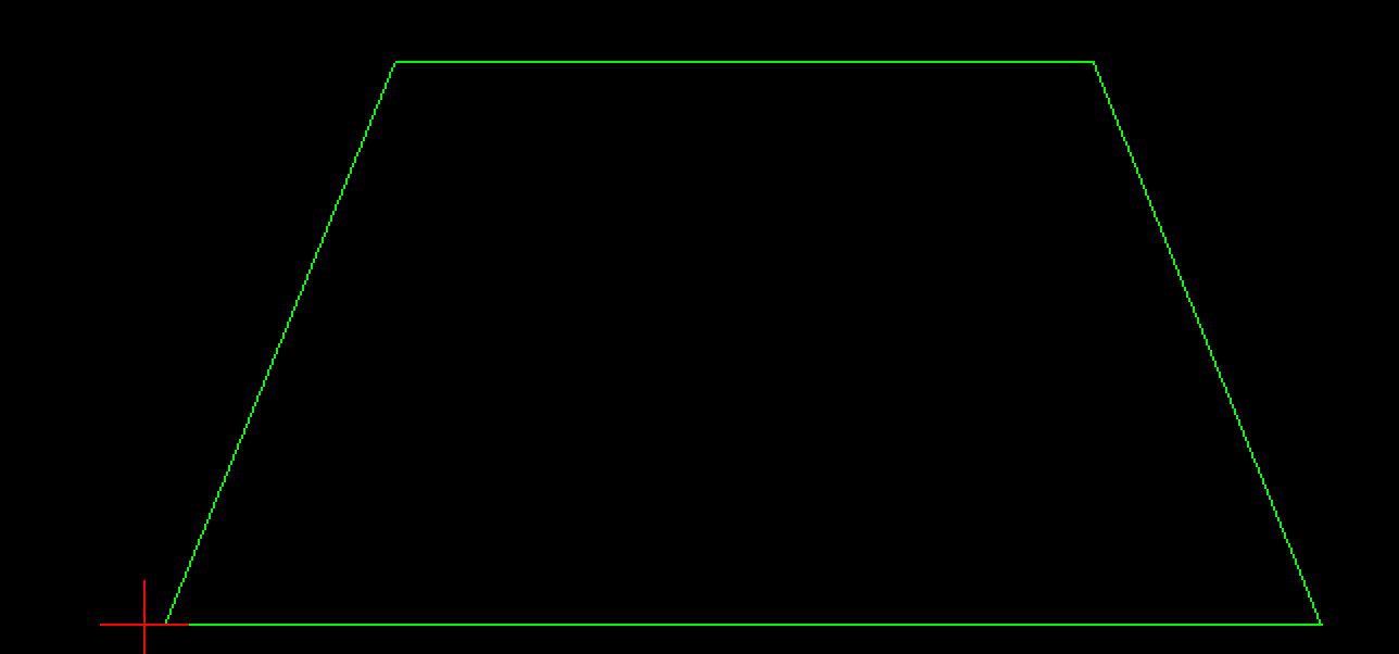
Everything looks fine but it still fails to properly calculate and create an internal offset based on CAM side cutter compensation. Why? The next image is the issue. The bottom right side corner is not really as it seems.
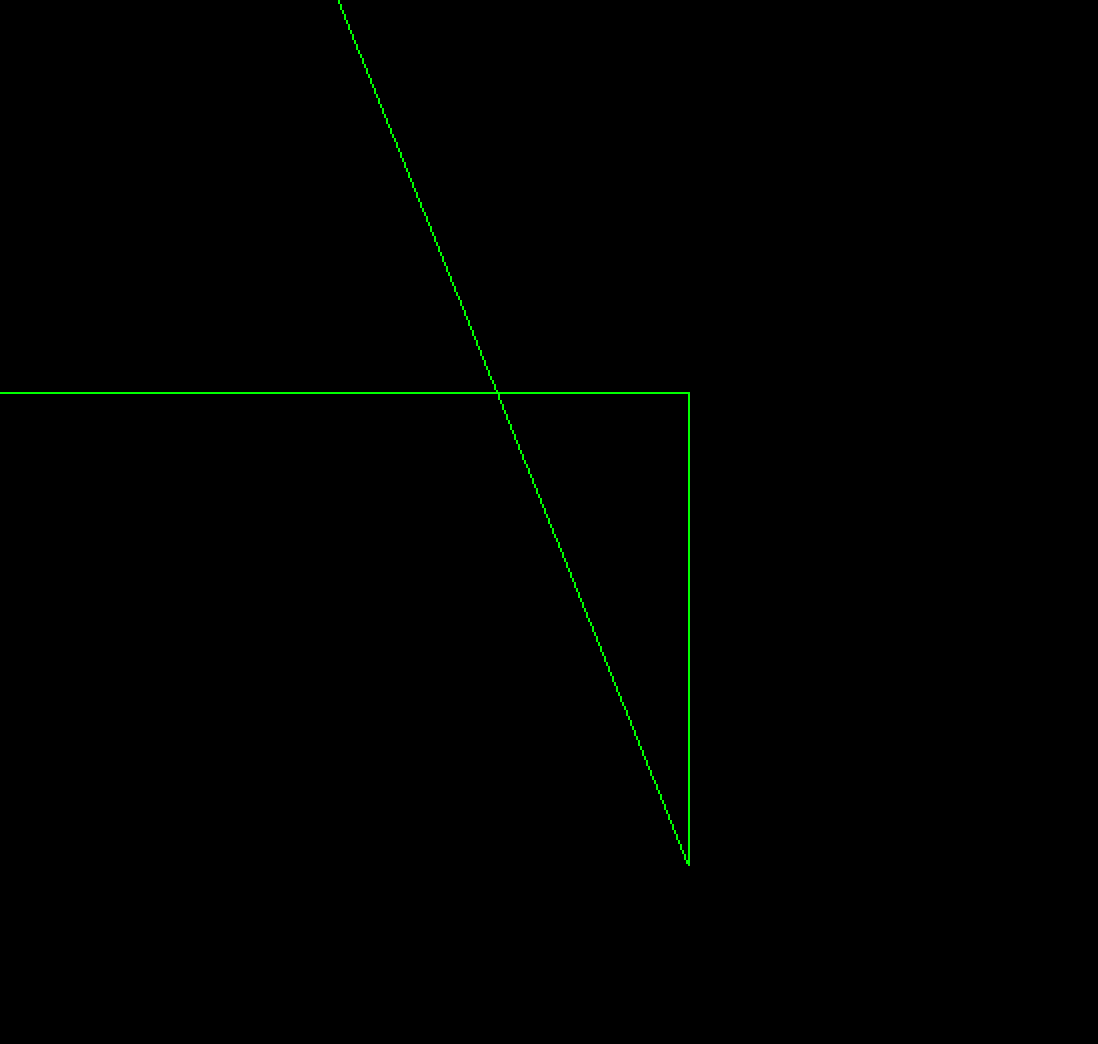
The corner has an extra ultra small line segment that creates a looping back crossed line situation. I have an algorithim that scans around a shape looking at a window of 3 line segments. geo1, geo2, geo3. If geo1 and geo3 intersect then we know geo2 is a problem so we remove it and realign geo1 and geo3 to link using the average of the delta between them. In most instance this change is no more than 0.05mm. But if the change is larger and can be seen in the resuling import then some manual correction is going to be needed in a LibreCAD or similar before import.
I'm still working on and testing this algorithm but the aim is to have it as an option that can be managed through the UIs config options.
Cheers - J.
If we consider a simple shape such as this:
Everything looks fine but it still fails to properly calculate and create an internal offset based on CAM side cutter compensation. Why? The next image is the issue. The bottom right side corner is not really as it seems.
The corner has an extra ultra small line segment that creates a looping back crossed line situation. I have an algorithim that scans around a shape looking at a window of 3 line segments. geo1, geo2, geo3. If geo1 and geo3 intersect then we know geo2 is a problem so we remove it and realign geo1 and geo3 to link using the average of the delta between them. In most instance this change is no more than 0.05mm. But if the change is larger and can be seen in the resuling import then some manual correction is going to be needed in a LibreCAD or similar before import.
I'm still working on and testing this algorithm but the aim is to have it as an option that can be managed through the UIs config options.
Cheers - J.
Attachments:
The following user(s) said Thank You: phillc54, snowgoer540
Please Log in or Create an account to join the conversation.
Time to create page: 0.152 seconds