simple linux cam
- Reinhard
- Offline
- Platinum Member
-

Less
More
- Posts: 508
- Thank you received: 94
30 Apr 2022 03:03 #241693
by Reinhard
Replied by Reinhard on topic simple linux cam
Hi,
thank you for your attention and your interest.
No, that is not an issue for me.
There are several reasons why I don't want to commit to freeCad:
That's why I decided to use a neutral format that can be written by all CAD systems. This makes me independent from CAD systems and my application can be used not only by freecad users.
As far as the missing binding to the CAD model is concerned, I even see this as an advantage (see above). My goal is to make the steps so simple that you can delete and recreate an operation at any time (currently: select drawing element, create operation, set machining parameters and select "create toolpaths". Toolpath creation can be executed at any machning parameter change). I plan to be able to show differences between model and product (sometime in the distant future - I'm at the very beginning of the project)
In addition, my focus is on the areas that are rather neglected by Hobby-cams. I do not intend to create a full-fledged CAM. Some things, like 3D surfaces, Deskproto already does better (which I think has very fair conditions for hobby use), other things are covered by CamBam or Estlcam.
I didn't find a cam to generate paths for my technical parts at that time, so had to program by hand. Such parts are my focus and I try to generate GCode as it is used in profesional environments.
Don't know if there is any interest in a product with my focus. We'll have to see.
Anyway, this is my way.
... by the way:
Suggestions, criticism and/or contribution are always welcome
thank you for your attention and your interest.
No, that is not an issue for me.
There are several reasons why I don't want to commit to freeCad:
-
- freeCad's data model is insecure and unstable. If you change something in history, the whole model gets corrupted and there is no way to recover.
Therefore (in my opinion) freecad is unsuitable for long term technical projects. I have been following freecad for many years and that basic model problem has not changed at all
- freecad has many very good developers and freecad has a very good collaboration mechanism (incl. code review). That would be a reason, but - each developer cares only about his agenda. There is no collaboration where a common path is followed. One or two developers (fortunately) have the whole project in mind. The rest just do their thing
- freecad is very python heavy and I don't like python!
- freecads developers are all much better in math and better than me - I am just a simple hobby coder
That's why I decided to use a neutral format that can be written by all CAD systems. This makes me independent from CAD systems and my application can be used not only by freecad users.
As far as the missing binding to the CAD model is concerned, I even see this as an advantage (see above). My goal is to make the steps so simple that you can delete and recreate an operation at any time (currently: select drawing element, create operation, set machining parameters and select "create toolpaths". Toolpath creation can be executed at any machning parameter change). I plan to be able to show differences between model and product (sometime in the distant future - I'm at the very beginning of the project)
In addition, my focus is on the areas that are rather neglected by Hobby-cams. I do not intend to create a full-fledged CAM. Some things, like 3D surfaces, Deskproto already does better (which I think has very fair conditions for hobby use), other things are covered by CamBam or Estlcam.
I didn't find a cam to generate paths for my technical parts at that time, so had to program by hand. Such parts are my focus and I try to generate GCode as it is used in profesional environments.
Don't know if there is any interest in a product with my focus. We'll have to see.
Anyway, this is my way.
... by the way:
Suggestions, criticism and/or contribution are always welcome
The following user(s) said Thank You: tommylight, MTronics
Please Log in or Create an account to join the conversation.
- Reinhard
- Offline
- Platinum Member
-

Less
More
- Posts: 508
- Thank you received: 94
02 May 2022 13:36 #241850
by Reinhard
Replied by Reinhard on topic simple linux cam
Hi,
With my project, I'm still at an early stage where I'm constantly questioning myself and my design decisions.
Following the mantra: "first make it work, then optimize" I'm still in the early stages of getting things to work. So far away from possible optimizations. Still, I'm not willing to use code that I'm already convinced is wrong or bad.
I only know the problems with freecad as a user. But I am aware that it is due to opencascade. I also had to realize that opencascade is not reliable at all. That's why I use opencascade only in the sense of "fire and forget", i.e. create ooct objects when I need them and immediately forget them again. I don't rely on occ datastructures at all!
I only rely on my own data and data structures.
I liked the structures of cavalier contours very much, but I had to realize that I am not skilled enough to adapt the library to my needs. So unfortunately I have to live without that library.
My data structures are redundant and consume much more memory than, for example, cavalier contours. Its because I understand my data structures only.
Maybe something can be optimized later?
Maybe I still learn and make friends with cavalier contour?
No idea what the future will bring.
For me, everything is new territory with which I am currently struggling.
Therefore - if you can tell me advantages that the data model of freecad can offer me, then please write that. I am open to any suggestion to seriously consider.
The following user(s) said Thank You: tommylight
Please Log in or Create an account to join the conversation.
- Reinhard
- Offline
- Platinum Member
-

Less
More
- Posts: 508
- Thank you received: 94
03 May 2022 16:02 #241928
by Reinhard
Replied by Reinhard on topic simple linux cam
Hi,
a small update.
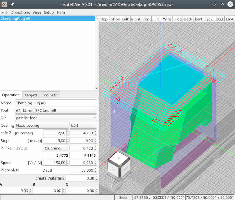
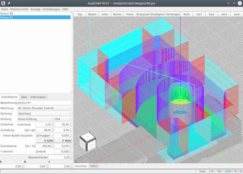
For 5-axis operations like this you'll need a clamping plug.
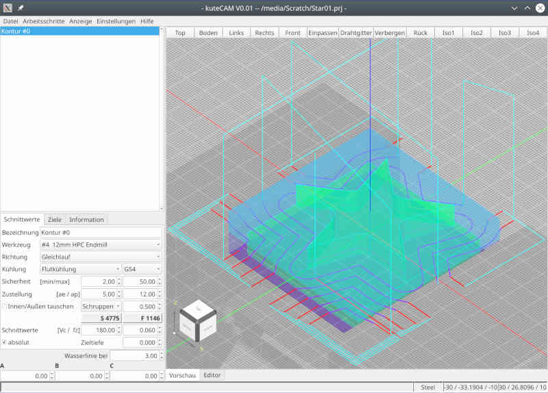
With the update, you can define the clamping plug on top and create milling paths for it:
To try the generated paths only little change is required. The generated gcode starts like this:
The line "M98 P100" is a subroutine call for tool change. Replace that line with "M6" and have fun
a small update.
For 5-axis operations like this you'll need a clamping plug.
With the update, you can define the clamping plug on top and create milling paths for it:
To try the generated paths only little change is required. The generated gcode starts like this:
( Job /media/Scratch/CP013.ngc );
( generated by kuteCAM V0.01 );
;
G40 G80;
T4;
M98 P100;
;
( ClampingPlug #0 );
( T4 12mm HPC Endmill - D:12 L:50 );
N10 G0 G90 G54 X-70.600 Y33.640 S4775 M3 T4;
G43 H4 Z61.000 M8;
The line "M98 P100" is a subroutine call for tool change. Replace that line with "M6" and have fun
Attachments:
The following user(s) said Thank You: tommylight
Please Log in or Create an account to join the conversation.
- Reinhard
- Offline
- Platinum Member
-

Less
More
- Posts: 508
- Thank you received: 94
08 May 2022 15:43 #242306
by Reinhard
Replied by Reinhard on topic simple linux cam
Attachments:
The following user(s) said Thank You: tommylight, silopolis
Please Log in or Create an account to join the conversation.
- silopolis
- Offline
- Junior Member
-

Less
More
- Posts: 23
- Thank you received: 4
25 May 2022 10:33 #243780
by silopolis
Replied by silopolis on topic simple linux cam
Hi,
First congrats for this very nice and promising work !
Very much like the clear and clean UX
Will follow closely...
Considering that main data model issue, topological naming, is slowly about to be fixed with the ongoing preparation of @realthunder's LinkStage branch, the first and huge benefit would be associative CAM ! Meaning toolpath would "follow" model modifications without having to be redefined. BIG BIG WIN !!!
It may seem fast and easy to re-create a toolpath but, IRL, it's not. it's tedious and error prone, in addition to being a loss of time.
About model stability, It must be noted that all CAD kernels suffer from that topo naming nightmare and just solve them better or worse. With the merge mentioned above, it seems that FreeCAD is on the road to do it quite well
On a side note, I've been bitten by this (broken CAM association due to topo naming inconsistency) many times in Fusion 360, and know it happens in SolidWorks and other too.
AFAIC, this by itself would be enough to favor FreeCAD. Then for the other points you raise, you can do as much C++ as you want in FreeCAD and only be constrained to glue code in Python. OTOH, Python environment could lower the bar for contributors. Finally, as you seem to struggle with math etc, I can't understand how joining an open and knowledgeable community can be problem !
I really encourage you to get in touch with Brad Colette (@sliptonic), of FreeCAD Path WB, and share views and ideas with him. And even more strongly now that he is joining the LinuxCNC community.
Keep it on anyway, exciting stuff
TY
J
First congrats for this very nice and promising work !
Very much like the clear and clean UX
Will follow closely...
Therefore - if you can tell me advantages that the data model of freecad can offer me, then please write that. I am open to any suggestion to seriously consider.
Considering that main data model issue, topological naming, is slowly about to be fixed with the ongoing preparation of @realthunder's LinkStage branch, the first and huge benefit would be associative CAM ! Meaning toolpath would "follow" model modifications without having to be redefined. BIG BIG WIN !!!
It may seem fast and easy to re-create a toolpath but, IRL, it's not. it's tedious and error prone, in addition to being a loss of time.
About model stability, It must be noted that all CAD kernels suffer from that topo naming nightmare and just solve them better or worse. With the merge mentioned above, it seems that FreeCAD is on the road to do it quite well
On a side note, I've been bitten by this (broken CAM association due to topo naming inconsistency) many times in Fusion 360, and know it happens in SolidWorks and other too.
AFAIC, this by itself would be enough to favor FreeCAD. Then for the other points you raise, you can do as much C++ as you want in FreeCAD and only be constrained to glue code in Python. OTOH, Python environment could lower the bar for contributors. Finally, as you seem to struggle with math etc, I can't understand how joining an open and knowledgeable community can be problem !
I really encourage you to get in touch with Brad Colette (@sliptonic), of FreeCAD Path WB, and share views and ideas with him. And even more strongly now that he is joining the LinuxCNC community.
Keep it on anyway, exciting stuff
TY
J
Please Log in or Create an account to join the conversation.
- silopolis
- Offline
- Junior Member
-

Less
More
- Posts: 23
- Thank you received: 4
25 May 2022 10:36 #243781
by silopolis
That was rude
Replied by silopolis on topic simple linux cam
i am not yet so desperate that i would accept such a stupid solution. I thought you were a math specialist, but something like this is - sorry - beginner level.
Maybe I can find a real math pro who is willing to help me.
That was rude
Please Log in or Create an account to join the conversation.
- Reinhard
- Offline
- Platinum Member
-

Less
More
- Posts: 508
- Thank you received: 94
06 Jun 2022 15:14 #244676
by Reinhard
Replied by Reinhard on topic simple linux cam
Attachments:
The following user(s) said Thank You: silopolis
Please Log in or Create an account to join the conversation.
- silopolis
- Offline
- Junior Member
-

Less
More
- Posts: 23
- Thank you received: 4
06 Jun 2022 20:14 #244688
by silopolis
Replied by silopolis on topic simple linux cam
Path for cylinder on a face tooks darn nice ! :+1:
Do you have an option to machine "by area" instead of "by depth" ? Could avoid a bunch of rapid moves, furthermore with a "stay down"...
I'll add kuteCAM to my translation backlog, already have @bigjohnt 's MesaCT waiting in line
Do you have an option to machine "by area" instead of "by depth" ? Could avoid a bunch of rapid moves, furthermore with a "stay down"...
I'll add kuteCAM to my translation backlog, already have @bigjohnt 's MesaCT waiting in line
Please Log in or Create an account to join the conversation.
- Reinhard
- Offline
- Platinum Member
-

Less
More
- Posts: 508
- Thank you received: 94
07 Jun 2022 14:05 #244722
by Reinhard
Replied by Reinhard on topic simple linux cam
Thank you for your attention and your flowers 
Keep in mind, that I'm at the very beginning of a huge project ...
I plan the application in such a way that the user selects some elements from the model and I, or rather kuteCAM, then knows what to do.
In no case I plan to reinvent a CAD.
Even though I am at the very beginning, I'm already very satisfied with my progress (I have very little sparetime) and so far I have been able to implement everything as planned. Therefore, I am confident and continue to follow my plans.
"Stay down" is an (important) option for finishing. So far, I am dealing exclusively with roughing and stay down is not important for roughing. My test models are intentionally complex enough to keep me busy with challenges in the long run.
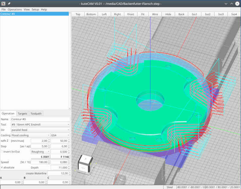
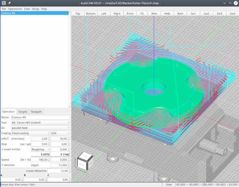
Currently, I am still working on implementing general purpose processing. So far from any optimization. To visualize the way my processing works, take this picture:
The dark blue lines are the "real workpath" where the tool should cut material. The red lines are "lead-in" and "lead-out" to ensure, that the tool is completely outside of the model. I extended the red lines for debugging purpose (just to be able to visualize the order of movements).
I cut the virtual working area into smaller areas and as long as the tool stays in one area, the tool will stay down.
For area changes, I move up to save retraction layer. That's a place for later optimization, but actually I don't waste a thought on it.
Looking back, I have to confess, that I lost most dev-time in debugging and understanding randomly/unpredictably results from occ and creating a reliable layer between occ and my app. Apparently occ has no interest supporting hobby users, so I have to fight my battle alone (not my preferred way of working)
So I'm not sure how much effort I'll still putting into occ. I have the impression by using occ it always goes one step forward and yet two steps back - or to put it another way: occ is the most expensive foreign library I have ever looked into. Even though I think I've understood quite a bit, I'm sure I've only lightly scratched the surface.
... so I have no idea where the journey will take me.
Keep in mind, that I'm at the very beginning of a huge project ...
Don't know what you mean with "by area" and don't know neither whether I got you right.Do you have an option to machine "by area" instead of "by depth" ? Could avoid a bunch of rapid moves,
I plan the application in such a way that the user selects some elements from the model and I, or rather kuteCAM, then knows what to do.
In no case I plan to reinvent a CAD.
Even though I am at the very beginning, I'm already very satisfied with my progress (I have very little sparetime) and so far I have been able to implement everything as planned. Therefore, I am confident and continue to follow my plans.
"Stay down" is an (important) option for finishing. So far, I am dealing exclusively with roughing and stay down is not important for roughing. My test models are intentionally complex enough to keep me busy with challenges in the long run.
Currently, I am still working on implementing general purpose processing. So far from any optimization. To visualize the way my processing works, take this picture:
The dark blue lines are the "real workpath" where the tool should cut material. The red lines are "lead-in" and "lead-out" to ensure, that the tool is completely outside of the model. I extended the red lines for debugging purpose (just to be able to visualize the order of movements).
I cut the virtual working area into smaller areas and as long as the tool stays in one area, the tool will stay down.
For area changes, I move up to save retraction layer. That's a place for later optimization, but actually I don't waste a thought on it.
Looking back, I have to confess, that I lost most dev-time in debugging and understanding randomly/unpredictably results from occ and creating a reliable layer between occ and my app. Apparently occ has no interest supporting hobby users, so I have to fight my battle alone (not my preferred way of working)
So I'm not sure how much effort I'll still putting into occ. I have the impression by using occ it always goes one step forward and yet two steps back - or to put it another way: occ is the most expensive foreign library I have ever looked into. Even though I think I've understood quite a bit, I'm sure I've only lightly scratched the surface.
... so I have no idea where the journey will take me.
Attachments:
The following user(s) said Thank You: silopolis
Please Log in or Create an account to join the conversation.
- Reinhard
- Offline
- Platinum Member
-

Less
More
- Posts: 508
- Thank you received: 94
08 Jun 2022 03:11 #244747
by Reinhard
Replied by Reinhard on topic simple linux cam
Hi silopolis,
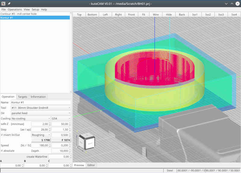
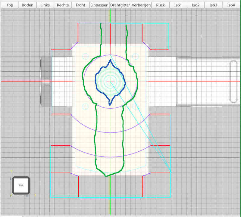
I took a closer look at cylinder job and how to optimize it. Regarding "stay low" - all movements for one z-height are already performed as "stay low", which means, changing Z happens only, when a new Z-height will be milled.
An alternate (shorter?) path might look like this (the green line) - from top view:
but I fear, that with this path, the cylinder is not round but something like the blue line. So I need a full turn around the cylinder anyway. Drawback of the green path - it works only as long as the workpiece is smaller that double the diameter of the tool.
My actual variant works for any shape and any dimension of the face below the cylinder.
So I think, a really shorter workpath could be created, if you don't care for cutting direction (alternating parallel feed and against feed).
What do you think?
Attachments:
The following user(s) said Thank You: silopolis
Please Log in or Create an account to join the conversation.
Time to create page: 0.458 seconds


