Encoders vs. Tachometers ???
- cmorley
- Online
- Moderator
-

- Posts: 7277
- Thank you received: 2120
When I read 'resolver' I think of a feedback device sometimes found on ac servo motors.
So I am assuming that the original system used servo drives that used tach feedback and then used the scales as the positional feedback?
Or are you piecing this together your self?
Peter is the owner of Mesa electronics - he is PCW on this forum.
here is the docs for linuxcnc:
www.linuxcnc.org/docs/2.5/html/
look there and you will find info on the PID component ( and everything else )
There is a pin on it that counts how long the PID has been saturated. You could add logic to this to set an estop after a certain amount of time.
I think that is what Peter was talking of (it's been a while since that conversation)
Of course Linuxcnc will also fault if there is a (positional) following error beyond (user selectable) specifications
As it is linuxcnc expects positional feedback not velocity feedback.
You have been asking for the easiest way to make this work - and the easiest way is to add a rotary encoder or use the scales.
If you are determined to use the analog velocity signal and have linuxcnc convert it to a positional signal be prepared to buy more hardware,
do some programming and probably still not be happy with the results. What I am saying is while I think (not that I'm an expert) it might be possible it is certainly not practical.
Thinking out loud is a great way to flush out ideas!
Please Log in or Create an account to join the conversation.
- jCandlish
-
 Topic Author
- Offline
- Senior Member
-

- Posts: 77
- Thank you received: 4
Yes.So I am assuming that the original system used servo drives that used tach feedback and then used the scales as the positional feedback?
Also, yesOr are you piecing this together your self?
As it is linuxcnc expects positional feedback not velocity feedback.
Is it EMC2 that expects this, or the 5i2x's FPGA?
Don't have emYou have been asking for the easiest way to make this work - and the easiest way is to add a rotary encoder
It will be interesting to see what happens in the drive belt failure error condition. PID tuning with only the scales must be very difficult.or use the scales.
If you are determined to use the analog velocity signal and have linuxcnc convert it to a positional signal be prepared to buy more hardware, do some programming and probably still not be happy with the results. What I am saying is while I think (not that I'm an expert) it might be possible it is certainly not practical.
I am determined to complete this conversion, and stand ready to take the necessary measures to do so.
Thinking out loud is a great way to flush out ideas!
Yeah, it helps greatly, and I thank this forum for the oportunity.
Rgds
_jC
.
Please Log in or Create an account to join the conversation.
- cmorley
- Online
- Moderator
-

- Posts: 7277
- Thank you received: 2120
I guess to be truly accurate linuxcnc needs both position and velocity - it just calculate velocity from position.
Trying to calculate accurate position from approximate velocity and time seems about impossible.
Well if the drive belt breaks then the axis can't really crash (it can't move) so thats not that bad.
The motor would spin at maximum.
worse is when the feedback device fails - but it doesn't matter what type of feedback device, if it fails the motor is going to try to move faster.
It would seem success of tuning with scales would depend on how much lost motion (backlash) between motor and axis and the resolution of the scales.
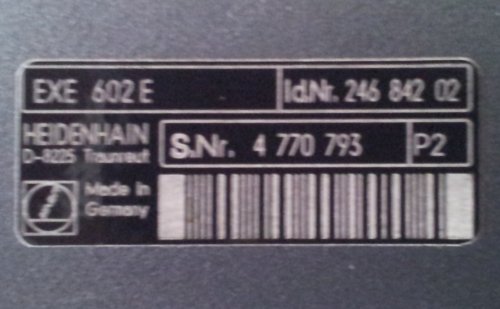
Typically you get way more resolution with rotary encoders because of the gearing and leadscrew. your interpolator helps here though I believe the 602 is usually 5x (though it can be 1x - it should say on the box)
you say you are ready to take the necessary measures to make this work you have three practical options that I see.
buy servo drives that use tach feedback and use the scales for positional feedback ( you won't use the 7i29 to drive the motors )
buy some encoders and add them either to the motor or the leadscrew. (this is the probably best option)
use the scales as feedback (probably hard to tune right)
And thats the end of my opinion !
Hopefully I haven't told you any big lies
Chris M
Please Log in or Create an account to join the conversation.
- jCandlish
-
 Topic Author
- Offline
- Senior Member
-

- Posts: 77
- Thank you received: 4
linuxcnc expects positional feedback ...
It would seem success of tuning with scales would depend on how much lost motion (backlash) between motor and axis and the resolution of the scales.
Typically you get way more resolution with rotary encoders because of the gearing and leadscrew. your interpolator helps here though I believe the 602 is usually 5x (though it can be 1x - it should say on the box)
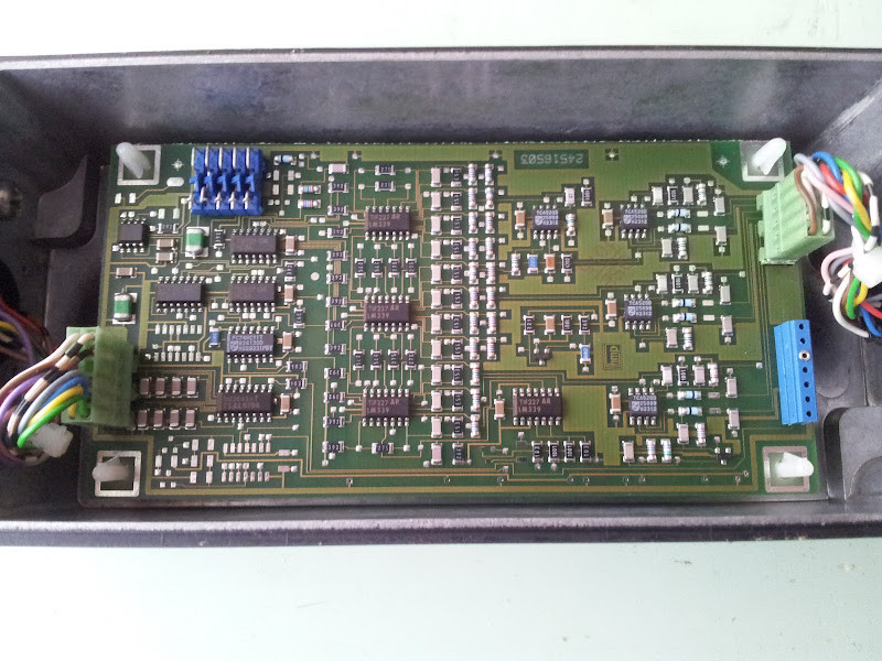
The machine has 32x5mm ballscrews, with 2/1 belting giving 2.5mm/rev at the servos. The HH scales are 20um and interpolate to 4um *hopefully I've go the right 602 units. It doesn't say on the box. The HH documentation states that the 602 is adjustable, but I can find no documentation for the jumper blocks. Maybe someone here knows?
you say you are ready to take the necessary measures to make this work you have three practical options that I see.
buy servo drives that use tach feedback and use the scales for positional feedback ( you won't use the 7i29 to drive the motors )
buy some encoders and add them either to the motor or the leadscrew. (this is the probably best option)
use the scales as feedback (probably hard to tune right)
And thats the end of my opinion !
Hopefully I haven't told you any big lies
Chris M
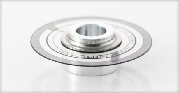
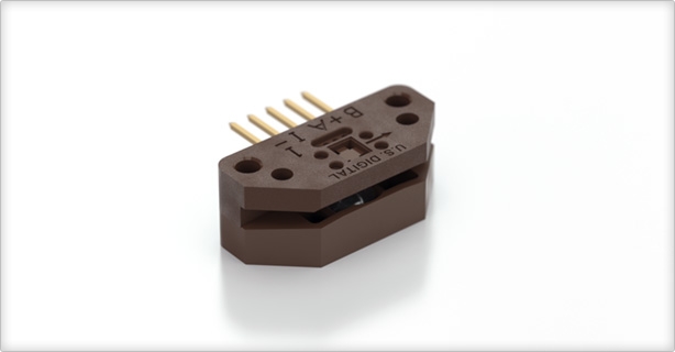
I'll take whats behind door #2 Chris. Say, optical encoders are butt cheap. USDigital has these that could be made to fit:
I would be interested to know of other suppliers as well.
With respect to interfacing the 7i29, the encoder connectors have pinouts for differential IDX,_IDX. I take it that those are optional.
Thanks again
John
.
Note to self: Don't try to post with the micron symbol.
Please Log in or Create an account to join the conversation.
- BigJohnT
-

- Offline
- Administrator
-

- Posts: 3990
- Thank you received: 994
Neat machine btw...
John
Please Log in or Create an account to join the conversation.
- andypugh
-

- Offline
- Moderator
-

- Posts: 19773
- Thank you received: 4601
In the end I want to close the servo loops with the glass scales on each axis of my mill.
I think that is the only way.
The existing Tachos on the motors connect to the servo drives, and will continue to do so. That allows the drives to work in a closed-loop velocity mode.
ie, 10V from LinuxCNC = 100% servo speed, 1V from LinuxCNC = 10% speed, 9v battery and no controller at all = 90% speed.
Then, inside LinuxCNC you run a position control loop which considers the feedback from the glass scales, and sends out a velocity command to the drives according to how far out of position the carriage is.
I hope that your glass scales have quadrature output though, or it gets a little tricksy.
Please Log in or Create an account to join the conversation.
- andypugh
-

- Offline
- Moderator
-

- Posts: 19773
- Thank you received: 4601
The existing Tachos on the motors connect to the servo drives, and will continue to do so..
I see now that you don't have tach-input drives, but intend to use Mesa H-bridges.
In theory this could be done. You would need to read the tachometer signal into LinuxCNC and use that to close a PID velocity loop, and then control position on a separate position PID loop. (Such nested PID loops are quite common outside the LinuxCNC world, and LinuxCNC can happily run dozens of PID components.
The problem, as you have spotted, is getting the Analog voltage into LinuxCNC. This is especially tricky in this case as the voltage is bipolar.
I think you could probably use an Arduino to do this on all three channels. The Arduino has several 0-5V analog inputs. Hopefully the Tachometers have two floating connections. You can hold one terminal at 1/2 Vref and then sample the other, then 0V sampled = -2.5V and 5V = +2.5V. You convert back to signed in the software. As the tachs go rather higher than 2.5V (If I recall correctly, I can't see back that far from this edit window) then you will _also_ need a voltage divider to bring the tach voltage in range.
Quadrature output from the Arduino is trivial, you just take the two lowest-order bits of a binary counter. So, you would measure the voltage (velocity) to create a target value, and then count up or down (in the main loop) a counter and put the two low-order bits on DIO pins. The analogue voltage would need to sample every mS, under interrupt.
As it happens I have nearly all of this ready-made here:
wiki.linuxcnc.org/cgi-bin/wiki.pl?ResolverToQuadratureConverter
That has the bipolar measurement, analogue-to-quadrature and interrupt-scheduled analogue captures all set up. You just need to take out the sine-wave generation parts.
Other options exist.
Please Log in or Create an account to join the conversation.
- cmorley
- Online
- Moderator
-

- Posts: 7277
- Thank you received: 2120
I remember when i got the manual for it - there was no mention of how to change it which to me meant you couldn't even though the docs seem to say you can.
You can buy other versions of the EXE that do other interpolation (ebay is your friend)
Andy the EXE converts the scales 11um sine waves to TTL signals so the scales are easy to connect to the 7i29.
Please Log in or Create an account to join the conversation.
- jCandlish
-
 Topic Author
- Offline
- Senior Member
-

- Posts: 77
- Thank you received: 4
In theory this could be done. You would need to read the tachometer signal into LinuxCNC and use that to close a PID velocity loop, and then control position on a separate position PID loop. (Such nested PID loops are quite common outside the LinuxCNC world, and LinuxCNC can happily run dozens of PID components.
Ah Andy, you have espied my cunning plan. And also found that pratice is different than theory.
The U.S.Digital encoder components seem to be quite a deal pricewise, 4 sets (1 spare) would be less than $150, and it does seem to be the most robust option in the feedback chain.
On the topic of the nested PIDs. I still intend to pursue this. That is why I asked about LinuxCNC having a native velocity component. 'cmorely' opines in a post about that the velocity component is derived. Does that mean that dV/dT and integral(dV/dT) are being calculated by LinuxCNC? I need to find time to look at that.
I still intend to use the HH scales for 'ground truth', even though their resolution is 1/4 that of the rotary encoders I suppose they are more accurate for a number of reasons.
cmorley wrote:
Yes, I'll cross that bridge when I get there. However the documentation I have is pretty clear that the interpolation is adjustable. There are jumper blocks in the device. Sadly, thats all I've got.It seems the exe 602E is either none or 5 fold interpolation. easy to check when you have it all hooked up.
With regared to the scales, the reference marks are documented as "Selectable by magnet every 50mm"? Does anyone here know how to perform this adjustment?
Its not over 'till its over.
John
.
Please Log in or Create an account to join the conversation.
- cmorley
- Online
- Moderator
-

- Posts: 7277
- Thank you received: 2120
look inside the housing you find a flat magnet that can be moved along the length of the scale.
it strengthens the index signal somehow.
if you figure out how to adjust the 602 please let me know - I had the manual for it and it didn't say how.
velocity is derived either from position and thread period or some of the hardware cards (Mesa and PICO) can supply a high quality velocity number.
They do this by using position and an internal time clock.
Please Log in or Create an account to join the conversation.


